This thread has been locked.

If you have a related question, please click the "Ask a related question" button in the top right corner. The newly created question will be automatically linked to this question.

ADS1298: Getting Straight Line as the input got saturated to its threshold

Part Number: ADS1298

The input channels are getting saturated as I have not using the RC level shifter at each input channels of ADS1298.  My reference voltages are AVDD +2.5V and AVSS -2.5V.  Earlier I was using a RC level shifter to set the baseline voltage to 1.2V and it was working fine all the time. But when there is no RC level shifter (which gives error in  lead off detection) the input differential band goes beyond the reference voltage so getting the values 0xFFFF in all the channel. 

Please help me to get the stable (constant) baseline with no RC level shifter circuit. 

When all 10 leads are connected to the subject to acquire 12 lead ECG the voltage band for each channel should be within the reference voltage all the time. Please help me to achieve this.

Thanks in advance. 

  • Hi Venkatesh,

    Can you please post a schematic? 

    Do you mean that your positive external reference voltage is (AVDD + 2.5V), and your negative reference voltage is (AVSS - 2.5V) or that the reference voltages are equal to AVDD and AVSS?

    Are you using the RLD function of the device? Correctly using RLD should help ensure that the measurement is within the common-mode range of the PGA. Alternatively, you can pull the inputs to mid supply using two large resistors. An explanation can be seen in this post: https://e2e.ti.com/support/data-converters/f/73/t/799662

  • Hi Alexander Smith,

    Thanks for the reply.

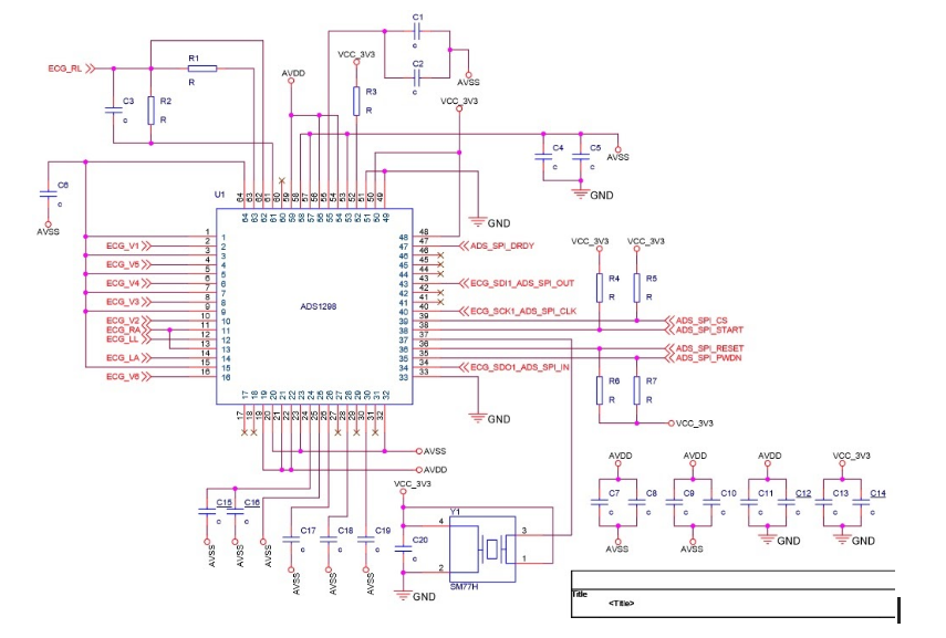
    AVDD = +2.5V and AVSS = -2.5V, DVDD(VCC_3V3) = 3.3V and using internal Reference voltage 2.4V.

    I have gone through the link you have shared in your answer. The R and C values I have used is C = 4.7uF and R1 = 1 MOhm(connected to AVDD), R2 = 2.2 MOhm(Connected to AVSS) this combination is creating issue for Lead off detection so decided to remove these R and C.  Or as you suggested in your reply C should be 100nF and R =10 MOhm, will this solve the lead off detection issue ?.    

    The circuit is taken from ADS1298ECG-FE Evaluation board schematic. I am not using the external reference for RLD input. Please let me know how we can configure proper RLD function.

  • Hi Venkatesh,

    Do you have schematic that shows the passive values and pin names? 

    I do not see where R1 is connected to AVDD. I see R1 being connected to RLDOUT pin 63 and the ECG RL net on your schematic. Are you referring to the picture in my reply? R9 and R17? 

    I would recommend disabling lead-off detection until all other functions of the device are working correctly.