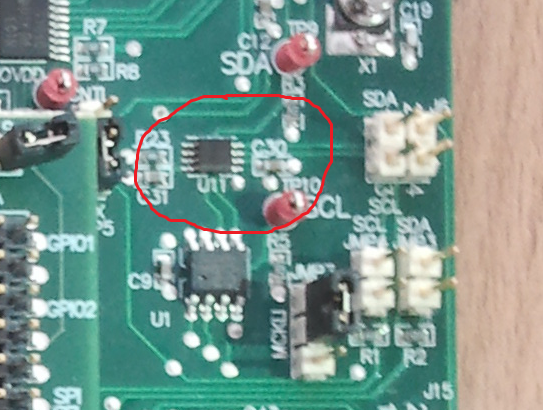
I have a TLV320AIC33EVM-PDK evaluation module, that includes an USB-MODEM INTERFACE board. I have downloaded from Internet datasheet for this board, but it have wrong an electric circuit diagram (for example, there is an U11 chip instead of Q1 and Q2 transistors). Where can I get a valid electric circuit diagram?
-
Ask a related question
What is a related question?A related question is a question created from another question. When the related question is created, it will be automatically linked to the original question.


