This thread has been locked.

If you have a related question, please click the "Ask a related question" button in the top right corner. The newly created question will be automatically linked to this question.

Wireless loopback testing with the AIC3254 - local loopback tests work, but wireless loopback fails...

Other Parts Discussed in Thread: TLV320AIC3254, TLV320AIC3204, MSP430BT5190

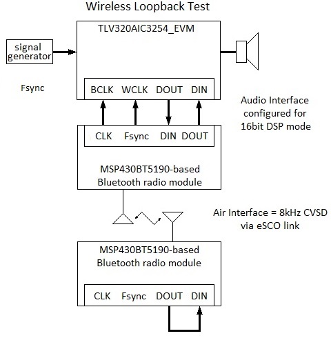
Can the TLV320AIC3254_EVM be configured (using the AIC3254 CS tool) to to support the wireless loopback test shown below?

Local loopback works fine.

The intention is to use the AIC32x4 to support various local effects (i.e. amplifying, mixing, filtering, and more) while separately bandwidth limiting and transmitting voice data from a selected microphone source. Only voice data will be transmitted via the BT radio.

The wireless loopback test is intended as one type of validation of the voice data part of the system.

Local loopback tests (using both the digital loopback mode as well as a physical jumper on the EVM DOUT/DIN pins) have been successful. However, these tests used the default processing blocks, which don't appear to tolerate signal delays between the ADC and DAC sides (this is a guess). The wireless [BT] loop generates very large delays, and so I'd like to configure a pass-though without filtering for this test. Is this possible? Is there something else going on here that can be addressed?

In tests of the wireless loop, the data returned to the EVM appear to be good with only a small amount of jitter in the least significant bits. This jitter is probably due to the CVSD compression.

I am using the AIC3254EVM-K Control Software and have successfully configured the EVM for local loopback tests. PurePath Studio is available, but I have not yet used it to generate any configuration scripts. The immediate goal is to achieve the best possible signal reproduction in a simple wireless loop before adding processing elements.

Thanks,

Tim

This past weekend I searched the forums again, which helped me to address some minor issues (such as ringing related to insufficient oversampling). However, I haven't yet found any notes/comments on why data returned to the Audio Interface by a wireless loop does not produce the same output as when digital loopback is enabled. A clear tone is obtained during digital loopback, but the audio output obtained via the wireless loopback is highly attenuated and contains noise. Any ideas on what might be happening here? The clock and data signals between the EVM and the radio I2S/PCM interface are clean.

From 2009: TLV320AIC3204: How to route the I2S data from ADC to DAC?

http://e2e.ti.com/support/data_converters/audio_converters/f/64/t/2462.aspx

From 2013: Configuring AIC3204 for 8Khz Mono ADC and also DAC

http://e2e.ti.com/support/data_converters/audio_converters/f/64/t/268902.aspx

  • Hi Tim,

    I can help you with issues related to the AIC3254. For the other devices, please refer to their respective forums.

    There should not be issues with delays. If you got it working with digital loopback then that probably means that the codec is working within itself. However, you need to make sure that the audio serial interface between the AIC device and Bluetooth I/F is configured correctly. Check the datasheet diagrams of both devices - the AIC3254 defaults to I2S, 16-bit, slave. Is the Bluetooth module compatible with this format? Also, check this app note http://www.ti.com/lit/pdf/slaa469 as well.

    Regards,

    J-


  • Hello Mr. Arbona - I've been reading all sorts of documents with your name on them recently, including SLAA469, which I used as a guide in configuring the AIC3254 in "ASI Slave Mode" (see Figure 4, page 4). Can you sign my copy of "How digital filters affect analog audio signal levels" and "Design and Configuration Guide for the TLV320AIC3204 and TLV320AIC3254 Audio Codecs?"

    Regarding my loopback issues: Yes, both digital loopback AND a physical loopback (in which a jumper is used between DOUT and DIN on the EVM) work, and the signals between the CODEC and the radio are clean. As a result of seeing this behavior on the CODEC side, I've been spending a lot of time on the radio side, but I felt a need to rule out other possibilities. The AIC3254 is something of a black box to me, and so I didn't know if, in default mode, there is any interplay between the ADC and DAC processing blocks that would somehow interfere with data looped back via the Audio Interface. Your reply indicates that this is not the case - okay, that helps me rule out that possibility.

    Since this is the audio converters forum I won't go into much detail on the radio here, but I have complete control over the Blueooth module (which is, essentially, a TI part...the MSP430BT5190) via HCI commands.

    Section 4.5.3 of TI document SWRS121B (Bluetooth and Dual Mode Controller) does a pretty good job of describing the radio's CODEC interface.

    I've been testing the PCM interface in various modes with dummy data (including using a bread-boarded microcontroller rig to output table data to generate BCLK, WCLK, and DOUT) and, basically, what I put in is what I get out, except when CVSD compression is used. CVSD, as far as I know, is lossy and exhibits "bit jitter" when fed a constant input, and I'm seeing jitter in the least significant bits, but I don't know what is "usual, reasonable, and customary." I can also see this jitter when I power down the analog blocks of the CODEC - which results in the Audio Interface continuously outputting the last ADC  value via DOUT (the jitter is seen on DIN).

    Can you confirm that the CODEC output is 16-bit two's complement? The scope trace looks like this is the case, but I need new glasses.

    At the moment, my situation is this:

    With digital loopback I can can hear the clear tone that is injected, but via wireless loopback I hear a sound that seems to have a component that tracks the original tone (which I  vary using a signal generator), but it is garbled like something heard in a bad 1950's sci-fi movie.

    I will go back and work through tests using mu-law and A-law encoding to see if that makes a difference and run through any other configurations that I can think of. I may also switch to I2S to see if that makes any difference.

    Please leave this thread open for a few days while I plow through this stuff and I will get back to you with the results.

    Thanks for responding to my post.

    Regards,

    Tim

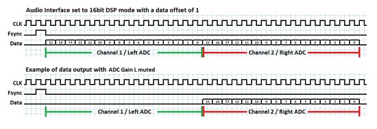
    Note: the CODEC and radio interface is configured for 16 bit data with a one clock cycle fsync and a data offset of one. Only channel 1 (left) is being processed by the radios. BCLK is continuous. This is what is programmed and what is seen (though, unlike this drawing, Channel 2 is flatlined):

  • Hello J-,

    It appears that the AIC3254 audio serial interface is performing properly and that the loopback failure is being caused by an air interface problem.
    The radio directly connected to the AIC3254 was placed in PCM loopback mode (digital loopback from the Bluetooth device) and the pure tone provided by the signal generator was correctly reproduced on the headphone outputs.

    Note for anyone else who may be using a BT radio with an audio codec: use the Vendor-Specific Write CODEC Config Enhanced command to disable retransmission of the last sample when no data is available. Retransmitting the last sample masked the problem I'm experiencing (approximately 50% of the data is being successfully transmitted per jump, resulting in about 25% getting back to the CODEC).

    So, J-, I will mark this post answered (solving it is up to me).

    A couple of questions:

    Situation: When using the AIC3254EVM-K Control Software (the "CS"), I have sometimes needed to repeat a command for it to work. As an example, I was testing a configuration using the analog bypass and got no output when power to a mixer amplifier was enabled. Toggling the Power checkbox resulted in the amplifier being enabled.

    Question: is this caused by the CS, or something else? In an embedded application, is it recommended to do a read-back on some types of commands to ensure that they have been processed?

    Situation: In my loopback tests I've used PRB_R1 (with adaptive filtering and Buffer A) and PRB_P20 (with adaptive filtering and Buffer B). Sometimes, when I first enable the analog power, the audio output is distorted, but by switching among the different processing blocks (somewhat randomly) and then back to the original configuration, the desired output is obtained. Note: any of the 0-biquad DAC processing blocks work in my tests - PRB_P20 has the lowest RC.

    Question: When using the processing blocks, is there a specific sequence that needs to be followed in programming them? Is the observed behavior related to the CS?

    General question: The ADC processing blocks work with stereo or the right channel, while the DAC processing blocks work with stereo or the left channel. Why?

    This affected me because the tests I'm doing use only one channel.

    Thanks for your help - your reply was useful in allowing me to rule out certain possibilities so that I could partition the problem set and focus my work.

    Regards,

    Tim

  • Hi Tim,

    Question: is this caused by the CS, or something else? In an embedded application, is it recommended to do a read-back on some types of commands to ensure that they have been processed?

    Not necessary unless you suspect there is an issue with I2C/SPI in the embedded platform (e.g. running too fast SPI, etc). If you power-up the blocks in the order of the signal path, then things should power up properly. For example, you should do the routing before powering up the amplifiers. In general, follow the sequence described in this app note: http://www.ti.com/lit/pdf/slaa473.

    Question: When using the processing blocks, is there a specific sequence that needs to be followed in programming them? Is the observed behavior related to the CS?

    I would not recommend switching PRB modes on the fly to avoid sudden artifacts. However, the distortion you mention is perhaps due to C-RAM not being configured properly for that PRB mode. There are some modes that have n-tap FIR filters. These would need prior configuration of C-RAM before powering up the device. In general, you can change PRB modes and write both C-RAM buffers if the PRB_XX is power down (i.e. ADC/DAC powered down). See http://www.ti.com/lit/pdf/slaa425 for details.

    General question:The ADC processing blocks work with stereo or the right channel, while the DAC processing blocks work with stereo or the left channel. Why? This affected me because the tests I'm doing use only one channel.

    Not sure exactly why. In terms of internal loopback test, you can select the left DAC datapath on p0_r63 to monitor the right ADC channel.

    Regards,

    J-


  • Hello J,

    Thanks - I appreciate the information!

    The intent is for this product to support different levels of field-programmability (by third parties, such as VARs). I'm not on the application side of things, but do have an interest / concern in how best to enable the greatest system flexibility for the app folks. The ability to load and run scripts is very attractive in this case.

    Maybe, when it's available, we should send an alpha or beta system to you to play with - if you're into that sort of thing.

    Regards,

    Tim

  • Hi Tim,

    "Maybe, when it's available, we should send an alpha or beta system to you to play with - if you're into that sort of thing."

    Perhaps a link for us to purchase the system would be better :)

    Regards,

    J-

  • First pass will be a modular bench-top development system - I'll send a note containing a discount coupon to you when there's hardware to play with.

    Regards,

    Tim