This thread has been locked.

If you have a related question, please click the "Ask a related question" button in the top right corner. The newly created question will be automatically linked to this question.

PCM1865 some questions?

Other Parts Discussed in Thread: PCM1865, PCM1861, PCM1863, TVP5158

Now we want to use PCM1865 combined with DM8168.

But I have some questions:

1.In datasheet,9.1.4 Main Audio ADCs..it says that 40KHZ adc.

   And in Page2 Typ.Performance it says that sampling frequency: 32KHZ to 192KHZ

   40KHZ audio,and 192K sr?I think sr=2*bandwidth.

   Is there something wrong?

2.Auto clock configure.

   If we are use PCM1865 in master mode,can pcm1865's clock be auto configured?

   I am a liitle puzzled,as it says that The dividers are auto configured based on clock rate detection in 9.13.3 of datasheet.How to detect clock rate?

3.Can I set PCM1865's sample frequency in 22.05K?

   In Page/Register 15

  there is not a case that sample frequency is 22.05K.Why?Can I set pcm1865's sample frequency to 22.05K?

BR!

  • Hello SuitJune,

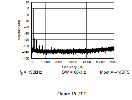
    1) So in the datasheet it says "The main ADCs in the PCM1861/3/5 are 110dB, 40kHz bandwidth ADCs..." however when it says 40kHz audio bandwidth it means at 110dB performance. The device can easily operate above that (up to 192k/2) but you will see a slow raise in distortion as you continue to increase the frequency. This can be seen in this figure 15 of the datasheet, pg 15

    2) Yes, you use the autodetection in master mode which will set the PLL dividers for you, however, it's usually recommend to set the values yourself if possible. This works by the device has an internal oscillator it uses as a reference to detect the frequency of the Mclk input and uses that to calculate the correct divider values. This auto dectection happens as a default and is configured using register 0x20 page 0.

    3) This is a bit confusing actually, since this isn't explicity stated in the datasheet, but register 115 page 0 is a read only register. This register will show you what the auto detection circuit measures the sampling rate at.

    22.05k sampling rate will work as long as you have all of the dividers properly configured.


    Hope this helps,

    Nate

  • Thanks for your detailed and effective reply.

    And I still have one question:

    for tdm mode in pcm1865,make pcm1865 to transfer 4 channel mono audio in tdm mode.

    According to the datasheet,we have to set BCK to 256fs.Why is 256?

    256=tdm slots*bits of a single sample?

    If BCK is 256fs.It there some padding in the audio buffer?I think 256fs's influence is that there are some extra useless data in the transfer.

    If I set it to 256Fs.And we use TI's DM8168's McASP to connect PCM1865.Does I need a extra modiy to alsa capture part code for the possible padding data?

    BR!

  • Hello SuitJune

    Where in the datasheet do you see you must run at 256*fs? I'm seeing a few tables that gives multiple options for Bclk.

    The rule with bit clock is that it needs to be greater than the data rate. So you end up with

    Bclk > tdm slots * bits of a simgle sample * fs

    If Bclk is greater than this it's still okay, it doesn't start reading zeros. If the audio is 16 bit, then it will read the 16 bits and the extra Bclks won't pull in any extra data. So as long as your offset is configured correctly you won't have any extra audio data coming it.

    Hope this helps! Please let me know if you have any other questions or would like any further explanation,

    Nate

  • Hi,in the page 76 of the datasheet,it says 256FS bclk is required for tdm mode.

    For the offset configuration,you mean the register I2S_TX_OFFSET?

    in the datasheet,it says that format must be dsp,then offset can be configured.

    But there is NOT a DSP format.

    So,I am confused.

    Follow your suggestion,you mean I can adjust the offset configure,then All the incoming data is NOT useless?For example,We capture 4 channel mono audio,and every channel sample is 16bit wide.Then the a whole frame is 16bit*4,But the BCK is 256FS=256 bit clocks,then there is 256-16*4=192 useless bit clock.So I can adjust offset to 193.Then all the incoming data is useful data.RIght?

  • Sorry for the confusion. Let me look into this some more and get you some more details and clarification.

    I'll touch base again ASAP,

    Nate

  • Hello SuitJune,

    Yes, the I2S_TX_OFFSET is what I was talking about. From the datasheet pg. 47

    The PCM1863 and PCM1865 are configured using register I2S_FMT (Page.0 0x0B). Register I2S_TX_OFFSET

    (Page.0 0x0D) should be used when dealing with TDM systems to offset the data transmit.

    In addition, the offset required for receiving 24-bit data can be programmed using RX_TDM_OFFSET (P0, R0x0E).

    When the datasheet states that it must be in DSP mode to use offset it's referring to TDM mode.

    I'll need to reach out to the design team to see exactly why 256*FS is required for BCLK, as in general all you need is > number of dout bits per FS. When using TDM you would want each channel to have a different offset to know which bits belonged to each channel. For example with 16 bit audio (16 for each left and right channel). The first channel would have an offset of 0, then the second channel would have an offset of 32, the 3rd channel would be 64, and the final would be 96. The extra bclks in that FS would not pull any extra data out of Dout, so there is no buffer necessary.

    I'll let you know what I hear back from the design team,

    Please let me know if you need any further clarification,

    Nate

  • thanks for your reply.

    But I still have some confusion.

    When the datasheet states that it must be in DSP mode to use offset it's referring to TDM mode.

    Still the question,there is no DSP mode configure in PCM1865.

     then the second channel would have an offset of 32, the 3rd channel would be 64, and the final would be 96

    I think the channel have an offset of 16 as PCM1865 could be configured as 4 channels mono audio adc rather than 4channels STEREO audio adc,all right,this does not matter too much.

    The extra bclks in that FS would not pull any extra data out of Dout, so there is no buffer necessary.

    As I think,the extra bclks in the FS,even there is no data ouo of Dout,it is 0 or 1 voltage level for the Dout pin,Then the bclks still toggles,so,there is a  fixed ''0 or 1' output for the Dout.I mean,Dout still outputs,but a useless data.

    Just like the cascaded TVP5158 audio connects to dm8168,there are some paddings for the audio output in the 256fs bclk case,so for the alsa audio capture,need to skip the unused audio padding data.

  • Hello SuitJune,

    I just heard back from the design team and they said that the 256*FS BCLK is required because in TDM mode this is fixed and not scalable. So the part was not designed to allow different BCLK speeds in TDM mode (you can still have different sampling rates and bit depths).

    When the datasheet states that it must be in DSP mode to use offset it's referring to TDM mode.

    Still the question,there is no DSP mode configure in PCM1865.

    When the device is configred as TDM mode, this is a DSP mode configuration. There isn't a separate mode for DSP. So you can think of when it says "only in DSP mode" it actually means "only in TDM mode" as these two are interchangeable in this datasheet (note: this is not the case in other datasheets). 

    then the second channel would have an offset of 32, the 3rd channel would be 64, and the final would be 96

    I think the channel have an offset of 16 as PCM1865 could be configured as 4 channels mono audio adc rather than 4channels STEREO audio adc,all right,this does not matter too much.

    Correct, in mono you would only need half the offset.

    The extra bclks in that FS would not pull any extra data out of Dout, so there is no buffer necessary.

    As I think,the extra bclks in the FS,even there is no data ouo of Dout,it is 0 or 1 voltage level for the Dout pin,Then the bclks still toggles,so,there is a  fixed ''0 or 1' output for the Dout.I mean,Dout still outputs,but a useless data.

    Just like the cascaded TVP5158 audio connects to dm8168,there are some paddings for the audio output in the 256fs bclk case,so for the alsa audio capture,need to skip the unused audio padding data.

    Okay, I think Im begining to understand what you are saying. Yes, the DSP (in this case the DM8168) would need to know to only look at the first 16*4 bits on Dout and ignore the other "data" as BCLK continues to toggle.

    Please let me know if you have any further questions,

    Nate