This thread has been locked.

If you have a related question, please click the "Ask a related question" button in the top right corner. The newly created question will be automatically linked to this question.

AIC3106 SINGLE ENDED LINE OUTPUT showing noise

Other Parts Discussed in Thread: OMAP-L138

AIC3106 connects to OMAP-L138 via I2S on TMDSEVML138 board. The stereo line outputs show noise.

AIC3106 registers are set in the following order:

 0x00=0x00
 0x01=0x80
 0x02=0x22
 0x03=0x40
 0x07=0x0A
 0x08=0xE0
 0x09=0x40
 0x0C=0x00
 0x0F=0x00
 0x10=0x00
 0x13=0x04
 0x16=0x04
 0x1B=0x00
 0x1E=0x00
 0x25=0xE0
 0x26=0x10
 0x2B=0x00
 0x2C=0x00
 0x3A=0x00
 0x48=0x00
 0x52=0x80
 0x5C=0x80
 0x56=0x09
 0x5D=0x09
 0x65=0x01
 0x29=0x50

Data input into DIN change in the following order:

 A. all zero
 B. 1kHz sin or cos
 C. all zero

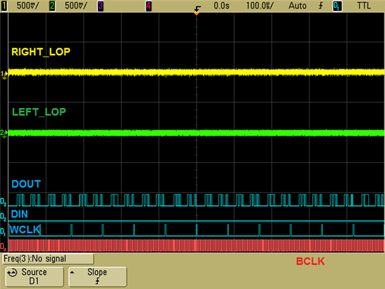
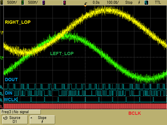
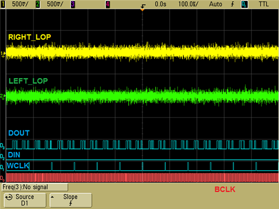
The traces of each A, B and C as follows:

 A. all zero


 B. 1kHz sin or cos


 C. all zero


Which of the register configuration or the board design is the cause of the noise caused by? If caused by the register configuration, how should it be fixed?

Best regards,

Daisuke


  • I have an additional question.

    LEFT_LOP/M Power Status bit in LEFT_LOP/M Output Level Control Register (Page 0 / Register 86) is read only. Similarly, RIGHT_LOP/M Power Status bit in RIGHT_LOP/M Output Level Control Register (Page 0 / Register 93) is read only. But these bits are set to 1 in some sample programs. If it is set to 1, the output trace changes.

    When LEFT_LOP/M Power Status bit is set to 0 and RIGHT_LOP/M Power Status bit is set to 1, the trace is as follows:

     Data of 1kHz sin or cos input into DIN.


    Should these bits not be set to 1 for normal operation?

    Best regards,

    Daisuke


  • Daisuke-san,

    This looks like normal out-of-band-noise. This is noise that is well above 20 kHz due to the delta sigma modulator. This can be filtered with an RC filter at the output.

    Have you tried looking at the output with a spectrum analyzer?

    Best Regards,

    dave

  • The Power Status Bit should be Read/Write. This is a mistake in the datasheet.

    They should be set to 1 for normal operation.

    Best Regards,

    dave

  • Hi dave,

    Thank you for your reply.

    AIC3106 on TMDSEVML138 does not have an RC filter at the output.

    I found the application report about the noise by the delta sigma modulator.

    http://www.ti.com/lit/an/slaa313/slaa313.pdf

    Does AIC3106 not have the internal filter to remove the noise? Is the external low-pass filter required?

    Best regards,

    Daisuke


  • Hi Daisuke-san,

    If the output of the AIC3106 goes directly to a speaker, typically, the filter is not needed since the speaker can not reproduce the high frequency noise (and it is outside of hearing range).

    If the output goes to a class-d amp or to test equipment with a wide-band input, then you should add an RC filter.

    Best Regards,

    dave

  • Hi dave,
     
    Thank you for your reply.
     
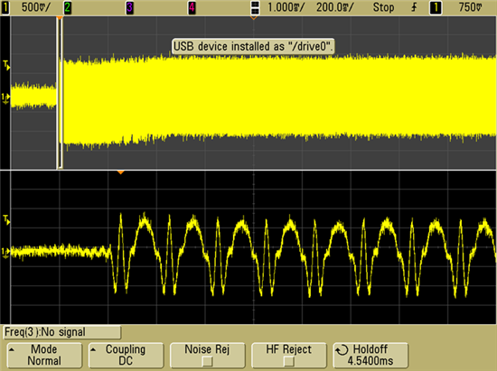
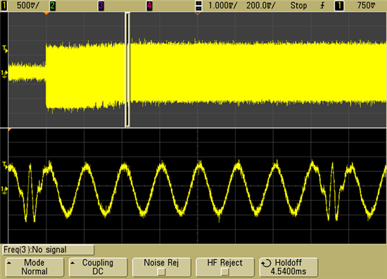
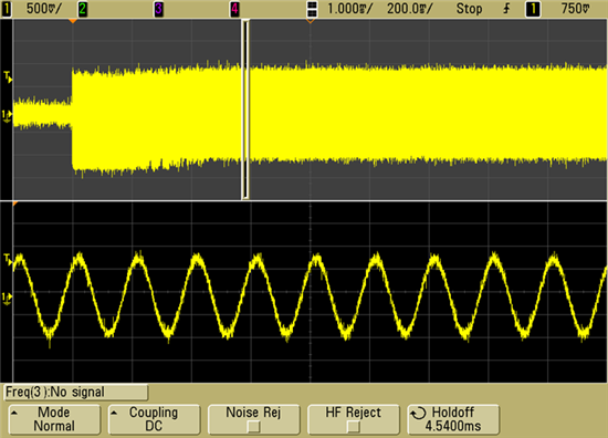
    There is other type of noise that distorts signals. After the data input into DIN changes from A to B, the noise is shown for a while. The common mode voltage seems to increase.
     
     A. all zero -> B. 1kHz sin
     AVDD_DAC = DRVDD = 3.3V, DVDD = 1.8V, CM SETTING = 1.35V, DAC VOLUME GAIN = 0 dB, LINEOUT GAIN = 0 dB
     DAC output selects direct path to line output driver.


    Best regards,
     
    Daisuke


  • Hi dave,

    The 1kHz sin input into DIN swings the full range in 16 bits word. Can you guess what the causes of this phenomenon are?

    Please give me an answer as soon as possible. Your prompt reply would be appreciated.

    Best regards,

    Daisuke


  • Hi Daisuke,

    It seems that the MSB is being interpreted incorrectly. Perhaps on one side of the digital interface is set for Left Justified and the other side is set to I2S?

    Best Regards,

    dave 

  • Hi dave,
     
    Thank you for your reply.
     
    Both sides of the digital interface are set to DSP mode. Our customer will check whether the digital interface signal is always stable.
     
    Best regards,
     
    Daisuke