This thread has been locked.

If you have a related question, please click the "Ask a related question" button in the top right corner. The newly created question will be automatically linked to this question.

Audio Inputs AIC3254

Other Parts Discussed in Thread: TLV320AIC3254

I have successfully created a system with the AIC3254 CODEC. However, I have found that when using two or more inputs IN1_L&R, IN2_L&R and IN3_L&R the different audio signals do not appear to 'Mix' properly. One channel appears to 'override' the other two. As the system relies on this function, it is very important. I have that some devices work fine and others not which suggest an 'Open' connection somewhere inside the device.

All the inputs are single ended with 1uF caps on the inputs. All signal levels are approximately 750mV P-P in amplitude. I have tried loads of different settings for the input routing registers 0x34, 0x36, 0x37 and 0x39 (page 1) without any success.

I have noticed that in the 'Design and Configuration Guide (SLAA404B)' that in section 2.7 there is a brief reference to a 'Programmable Voltage' being applied to the CM inputs. There is no further info describing how or where to do this. I have assumed that this automatically done via the MIC Bias voltage.

I cannot find any detailed information on how to connect multiple inputs to the device. Neither how to 'correctly' route the signals or how to use the 'MICPGA' properly.

I have noticed that in section 5.3.28 of the Application Reference Guide that the title refers to the 'negative' Input of the MICPGA where the text in the table refers to the 'Positive' input.

  • Hi Howard,

    You should be able to mix up to 4 single ended inputs per channel.

    The input architecture of the TLV320AIC3254 is of a fully differential amplifier. More information on this type of amplifier can be found here http://www.ti.com/lit/an/slyt310/slyt310.pdf and here http://www.ti.com/lit/an/sloa054d/sloa054d.pdf.

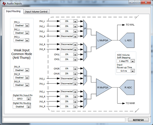
     Below is an example configuration you can use:

    This script will configure the part for such configuration:

    w 30 00 01
    w 30 34 A8
    w 30 36 42
    w 30 37 A8
    w 30 39 81

    The programmable common mode explained in the app note that you mentioned is located in p1_r51. As you can see from the drawing above, the inverting inputs (M) are connected to CM1L, CM2L, CM1R, CM2R which in turn are connected to the internal common mode voltage source of the part. Due to the fully differential architecture, you would need to configure the M side to have the same effective impedance as the P side. In this example the P side has three 20k resistors in parallel, which is the same as one 10k resistor and one 20k resistor in parallel as shown in the M side.

    It is not a requirement to have both P and M sides with the same effective impedance, but it helps in obtaining a predictable effective gain value (assuming that all inputs are tied to a voltage source at all times). If you plan to mix in external inputs on the fly such as audio in plugs, etc. you might consider adding buffers for each input to keep the source impedance seen by the AIC3254 inputs constant at all times.

    Let me know if this answers your questions.

    Regards,

    J-