This thread has been locked.

If you have a related question, please click the "Ask a related question" button in the top right corner. The newly created question will be automatically linked to this question.

Run time update of ADC A-B Coefficients Issue

Hello,


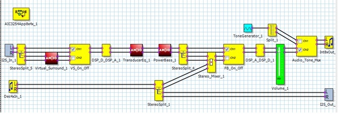
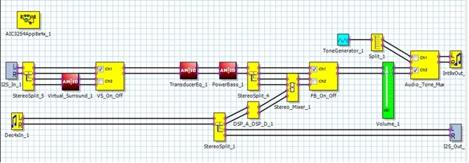
I have been working with AM3D regarding their virtual surround component. I had an issue where I could not compile with their components unless I disabled their “center speaker enhancement”. That is when they showed me how to change target of different components so that it would compile. However, this caused another issue where with their new scheme I could not vary the value of the Bass coefficient in another component (Power Bass). Yet I use to be able to vary it. Below is a brief description of what I have done.


Modified to allow center enhancement:


Control

I2C Page

I2C Reg

VS_On_Off

44

8

PowerBass

8

12

FB_On_Off

8

76

Master_Volume

44

32

Audio_Tone_Mux

44

52


Back to original design which doesn’t allow center enhancement:


Control

I2C Page

I2C Reg

VS_On_Off

44

56

PowerBass

44

12

FB_On_Off

44

100

Master_Volume

44

104

Audio_Tone_Mux

44

124


I am not sure why I have this issue but I am guessing that it is because I want to change this during run time I need to update Coefficient A and B for DAC (Page 44 , reg 1) and for ADC(page 8, reg 1). It appears that the scheme works for DAC but not ADC,. However given my limited experience with codecs it might be that there is another step involved when doing this for registers on page 8.


Here is the code snippet for varying the Bass Volume:


if(ParamMode == BASS_MODE)

{

                                BassIndex = Index;

                                if(BassIndex > 96)

                                                BassIndex = 96;

                                AIC3254_I2C_PAGE_WRITE(BV_Reg, BV_Page, &(AIC3254_Bass[BassIndex/4]), 4);             // Write Volume

                                   AIC3254_I2C_WRITE(0x00, BV_Page);                                                                                                   

                                   AIC3254_I2C_WRITE(0x01, 0x05);                                                                            

                                   while(AIC3254_I2C_READ(0x01)&0x01);                                   //Wait for D0 of Page BV_Page  reg 1 to be zero

                                   AIC3254_I2C_PAGE_WRITE(BV_Reg, BV_Page, &(AIC3254_Bass[BassIndex/4]), 4);      // Write Voliume again

                                   BassIndex = Index;

                   }

Where


BV_Page and BV_Reg is from the above tables dependent on which design I am using.


Have any of you ever seen this kind of issue?


Thanks,

Angelo

Modified Purepath design

Original Purepath design


  • Angelo,

    Are you able to change the bass coefficient using PurePath Studio and EVM (instead of the MCU)? I am trying to narrow down the problem to see if the issue is the process flow or how the buffer swaps are implemented in the MCU.

    Thanks,

    J-

  • Hello J Arbona,

    Sorry for the delay in response but quite busy with other parts of the project.

    Instead of trying it on the EVM with Purepath I have sniffed the I2C communication between the MCU and the AIC3254. You can see that the trace is identical other than the I2C page value.

    Modified to allow center enhancement:

    Original design doesn’t allow center enhancement:

    W30 00 08 STOP

    W30 00 2C STOP

    W30 0C 08 13 85 00 STOP

    W30 0C 08 13 85 00 STOP

    W30 00 08 STOP

    W30 00 2C STOP

    W30 01 05 STOP

    W30 01 05 STOP

    W30 01 STOP

    W30 01 STOP

    R31   06

    R31   06

    W30 00 08 STOP

    W30 00 2C STOP

    W30 0C 08 13 85 00 STOP

    W30 0C 08 13 85 00 STOP

    0.226s no I2C communication

    0.226s no I2C communication

    W30 00 08 STOP

    W30 00 2C STOP

    W30 0C 09 0F CC 00 STOP

    W30 0C 09 0F CC 00 STOP

    W30 00 08 STOP

    W30 00 2C STOP

    W30 01 05 STOP

    W30 01 05 STOP

    W30 01 STOP

    W30 01 STOP

    R31   06

    R31   06

    W30 00 08 STOP

    W30 00 2C STOP

    W30 0C 09 0F CC 00 STOP

    W30 0C 09 0F CC 00 STOP

    63ms no I2C communication

    63ms no I2C communication

    W30 00 08 STOP

    W30 00 2C STOP

    W30 0C 0A 2A DB 00 STOP

    W30 0C 0A 2A DB 00 STOP

    W30 00 08 STOP

    W30 00 2C STOP

    W30 01 05 STOP

    W30 01 05 STOP

    W30 01 STOP

    W30 01 STOP

    R31   06

    R31   06

    W30 00 08 STOP

    W30 00 2C STOP

    W30 0C 0A 2A DB 00 STOP

    W30 0C 0A 2A DB 00 STOP

    I hope that this helps.

    Thanks,

    Angelo

  • Hi Angelo,

    Looks like the buffers are swapping properly based on your reads.

    Could you try the same using PPS directly with the EVM. I am trying to determine if the issue is due to the AM3D component or your system.

    Thanks,

    J-


  • Hi J

    I tried it on the EVM-K and using PPS.  I had to modify AIC3254App8x4x_1 source from the one I use in my board I can supply you with that if you think it is necessary.

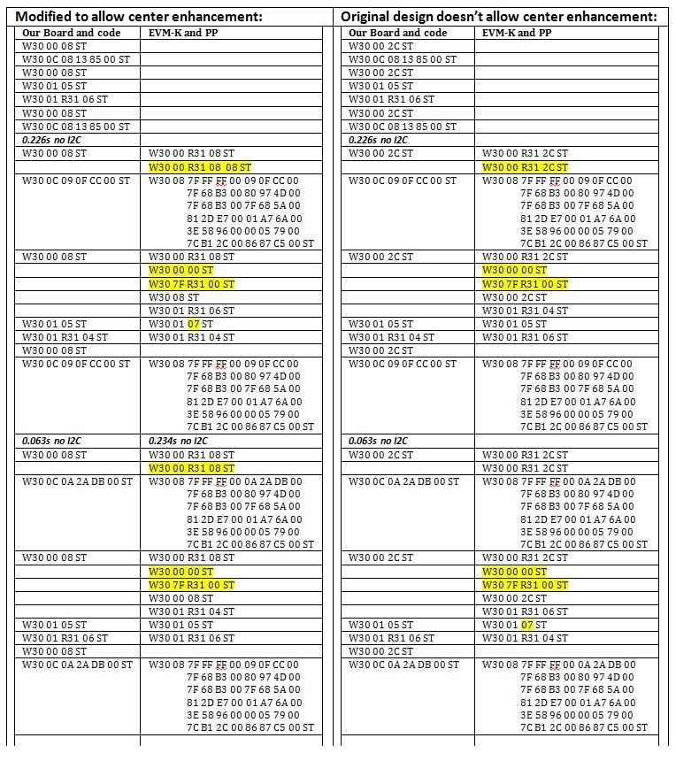
    I have attached an image of the differences in I2C communication between the different setups.  The high lighted parts are the differences that I don't understand.

    Thanks,

    Angelo

  • Angelo,

    So, does it work properly when using PPS and EVM-K?

    Thanks,
    J-
  • Hi J,

    Sorry, yes it does.

    However, I am not sure what is wrong with my versions communication?
    Why is [0x00][0x7F] being read?
    Also why does the EVM PPS version sometimes write 0x05 and at other times writes 0x07 at [0x08 (or 0x2C)][0x01]?

    Should I send AIC3254App8x4x_1 source?

    Thanks
  • Angelo,

    You can ignore the 7F read (that is user by newer parts to determine active Book).

    You can write 0x05 all time. PPS keeps track of the active buffer, but this is not needed because that bit is a read only flag.

    Regards,
    J-
  • Hello J,

    So what can be the cause of the problems that I am having? Where do I need to look next?

    There are still some differences from the EVM and our board as far as which IOs are using.

    Also, on our board we need to use the PLL since we are supplied via an external source a MCLK of 16MHz.

    I am attaching the IMAGE files for the EVM modified version using PPS  and My board modified version using an MCU.

    I hope this helps determine where the issue is.

    Thanks,

    Angelo

    aic_main - Modified EVM-K PPS.docxaic_main - Modified Our Board MCU firmware.docx

  • Hi Angelo,

    The ADC_CLK is out of spec for your target configuration.

    I recommend the following PLL settings for 16MHz MCLK and 48ksps:

    R = 1

    P = 1

    J  = 6

    D = 1440

    NDAC = 2

    MDAC = 8

    NADC = 2 (divider powered off)

    MADC = 8

    AOSR = 128

    DOSR = 128

    On PurePath Studio, I assume the cycles property of the framework is set to 1024.

    Regards,

    J-

  • aic_main - Modified as to J's suggestion.docxHi J,

    I implemented what you said. However I have AOSR set to 256 (0x00) because I need the input sampling at 24kHz.

    The cycles properties were set to 696 which is the lowest I could set it to and still have a successful build.

    The reason I am trying to reduce the cycles is because I have a very strict current budget and was told by TI that one way is to reduce the cycles as much as possible.

    That being said I put the cycles to 1024 in an attempt to solve this issue but I still have the same problem.

    I am attaching the resulting image file in case I have misunderstood what I should have done.

    Thank,

    Angelo

  • Hi Angelo,

    For 4x decimation, only AOSR = 128 or 64 are supported. Otherwise, you will get a gain error of +24dB after the decimator. You can reduce AOSR to 128 and increase MADC to 16 to reduce the sample rate to 24ksps.

    From the screenshot you provided, I noticed that you use the interprocessor component. Note that if you use that component both ADC and DAC sample rates must be the same. So having ADC = 24k and DAC = 48k is not supported when using this component.

    With regards to audio issues, I suggest as a next step to write exactly the same I2C commands that were generated by PPS. Replicating the same commands should solve the issue (assuming clocking as mentioned above is correct as well).

    Regards,

    J-

  • Hi J,

    I changed the AOSR for 128 (0x80) instead of 256 (0x00) and know it appears to update the coefficients properly (at least changing the Bass gain makes a noticeable change to the audio). However my system current consumption jumped from 33.2mA to 40mA.

    At any rate I consider the initial issue solved. Should I start a new thread for the current consumtion?

    Thanks,
    Angelo
  • Hi Angelo,

    Yes, please.

    Regards,
    J-