This thread has been locked.

If you have a related question, please click the "Ask a related question" button in the top right corner. The newly created question will be automatically linked to this question.

TLV320AIC3254 HP and LO impedance

Hey

We use multiple codecs where the outputs are mixed with a simple resistor network. Because the output impedance of the HP & LO are different, there is an imbalance of the mixing. So what is the "input" impedance of the output amplifiers (HPL, HPR, LOL & LOR)?

Does the impedance change when powering off the output amplifiers?

BR

Asger Hansen

  • Hi Asger,

    The LO drivers are not meant to drive anything less than 10k-ohm. So if you use a lower resistor values you might see signal attenuation. I don't have the exact number for the output resistance of the LO drivers, but it can be measured by driving a 500-ohm resistor or so and calculating the resistance based on the observed voltage drop.

    What values are you currently using for this summer circuit?

    Regards,

    J-

  • Hey

    Thanks for your fast answer, though i don't really understand it.

    In the datasheet (SLAS549D) under 10.3.2.4 Line Outputs, it says:

    "The stereo line level drivers on LOL and LOR pins can drive a wide range of line level resistive impedances in the range of 600Ω to 10kΩ."

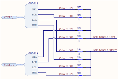
    Our mixing circuit looks like this

    SPK_TOGGLE_LEFT and SPK_TOGGLE_RIGHT goes to IN1_L and IN1_R respectively on a third codec that is configured for analog bypass (IN1 -> HP), which should have 6.6kΩ (+/- 20%) input impedance according to http://e2e.ti.com/support/data_converters/audio_converters/f/64/t/359715.

    Also the impedance of the LO seems to change when they are powered off, which means that we can't power them off when not in use.

    BR

    Asger

  • Hi Asger,

    Quick question, is SPK_TOGGLE_LEFT ac-coupled? What kind of load is present at that net?

    Regards,

    J-

  • Hi,
    Yes, SPK_TOGGLE_LEFT is ac-coupled through a 1uF capacitor to IN1_L on a third AIC3254 which is configured for analog bypass (i.e. IN1_L to HPL) which should have an input impedance of 6.6kΩ according to e2e.ti.com/.../359715.
    The same goes for SPK_TOGGLE_RIGHT which is ac-coupled through a 1uF capacitor to IN1_R on the third AIC3254.
    BR,
    Asger
  • Hi Asger,

    I should be getting exact data on the output impedance of the LO driver soon. HP driver is 0.5 to 1 ohm when powered.

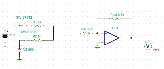
    On the third AIC3254, the IN1 to HP bypass amp is a simple inverting amp, so nothing special. However, note that in a summer amplifier configuration you would use its feedforward resistors for mixing. However, in this case there is a 6.6k resistor in series as well, so it is not a true summer amplifier (i.e. it is not G1*v1 + G2*v2 + G3*v3...) so you should expect some 'imbalance in the mixing'. As an example, if you have two inputs V1 and V2 with summing resistances R1 and R2 then the current into the amplifier (Iin) becomes a bit more complex (note that Rin below is the amplifier 6.6k input resistor).

    Note that Vout = -Iin x Rout

    where Rout = 6.6k as well, depending on the HP amp gain.

    Regards,

    J-