This thread has been locked.

If you have a related question, please click the "Ask a related question" button in the top right corner. The newly created question will be automatically linked to this question.

About AIC3268 control

Dear Sirs

        Customer use AIC3268 Demo board (Digital Microphone function) for DigiMic function.

By datasheet setting as follow (use DigiMic1 Left channel,GPIO1 is Data In,GPIO2 is Clock Out)


         Book 0,Page 4,Reg 87,Value 0x28

         Book 0,Page 0,Reg 81,Value 0xD0

         Book 0,Page 4,Reg 100,Value 0x00

         Book 0,Page 4,Reg 101,Value 0x00

         Book 0,Page 4,Reg 86,Value 0x04

 But the DigiMic function does not work.

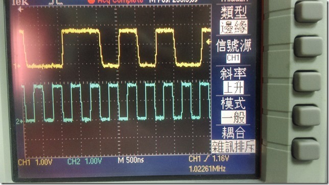
They measure digital mic wave as follow:  CH1 is Data,CH2 is Clock(Freq is 2.048Mhz).

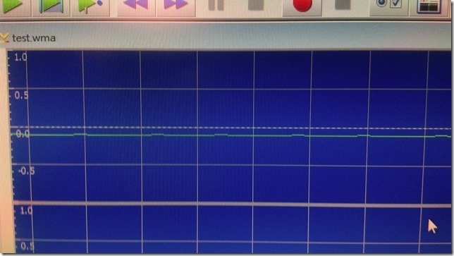
Record pattern from I2S.

Could you do me a favor to suggest any support?

BRS

Nat

  • Hi Nat,

    We are looking into this. In the meantime, can you check if the clock and data and supply signals are present on the actual digital microphone pins?

    Thanks,
    J-
  • Hi Nat,

    Please try the following code:

    # Enable all analog blocks
    w 30 7f 00
    w 30 00 01
    w 30 01 00
    
    # Set up clocking
    w 30 00 00
    # Power up NADC and MADC
    w 30 12 81 84
    # Program AOSR = 64
    w 30 14 40
    
    # Set GPIO2 to drive digital mic clock as ADC_MOD_CLK (Clock Frequency = AOSR*ADC_FS)
    w 30 00 04
    w 30 57 28
    # Digital Mic1 left on rising-edge of ADC_MOD_CLK, right on falling-edge of ADC_MOD_CLK
    w 30 64 44
    # Digital Mic1 left and right channel data pin = GPIO1
    w 30 65 00
    
    # Digital Mic1 is enabled on Left and Right CIC Filters
    # Power and Unmute up the stereo ADC channel
    w 30 00 00
    w 30 51 D4

    This configures GPIO2 as digital mic clock and GPIO1 as data. Make sure jumpers are set to their default according to Chapter 5 of the TLV320AIC3268EVM-U User Guide.

    Also, make sure the board you are using is RevC.

    Regards,

    J-