Hello all,
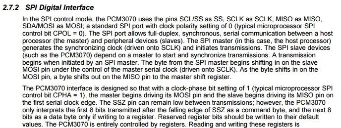
I'm trying to program the registers of a pcm3070 using a spi bus b3 on a msp430. With the following code. Unfortunatly, It doesn't work, Could you please help me?
Thank you in advance
void config_spi(void){

	///P1OUT |= 0x02;                            // Set P1.0 for LED
	                                            // Set P1.1 for slave reset
	  ///P1DIR |= 0x03;                            // Set P1.0-2 to output direction
	  ///P3SEL |= 0x31;                            // P3.5,4,0 option select
	  ///PASEL |= 0xE;
	  P2DIR |= BIT5+BIT4+BIT2;         /// Configuration Output SSZ, CLK_B3->Pin 2.4 ; SIMO_B3-> Pin 2.2 ;
	///  P2REN |= BIT3;  // P2.3 PullUp/PullDown enabled
	///  P2OUT &= ~BIT3;  // P2.3 PullUp selected
	  P2DIR &= ~BIT3; 				  //  Config SOMI_B3-> Pin 2.3 input
	  P2SEL |= BIT2+BIT3+BIT4;       ///  CLK_B3->Pin 2.4 ; SIMO_B3-> Pin 2.2 ; SOMI_B3-> Pin 2.3


	  UCB3CTL1 |= UCSWRST;                      // **Put state machine in reset**
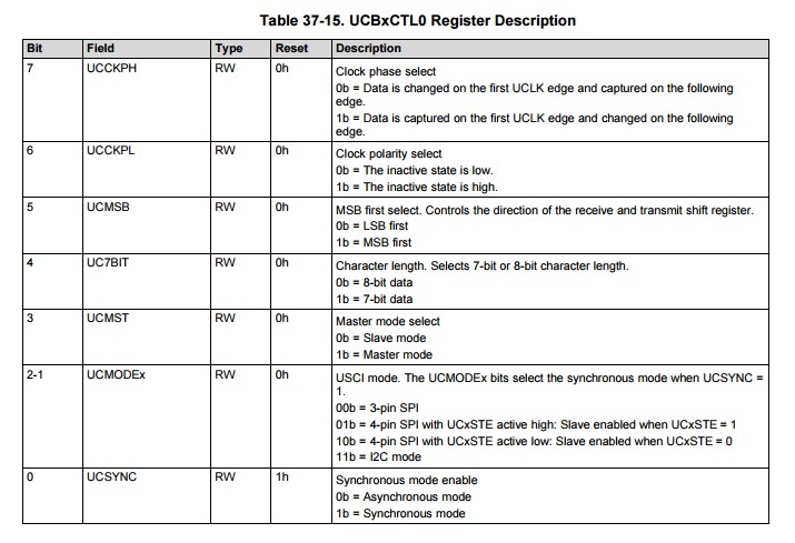
	  UCB3CTL0 |= UCMST+UCSYNC+UCMSB+UCCKPH;    // 3-pin, 8-bit SPI master ///UCMST+UCSYNC+UCCKPL+UCMSB;
	                                            // Clock polarity high, MSB
	  UCB3CTL1 |= UCSSEL_2;                     // SMCLK  UCSSEL_2
	  UCB3BR0 = 0x02;///0x02;                           // /2
	  UCB3BR1 = 0;                              //
	  UCA0MCTL = 0;                             // No modulation. Just needed on UCA0, no on ucb3
	  UCB3CTL1 &= ~UCSWRST;                     // **Initialize USCI state machine**
	  UCB3IE |= UCRXIE;                         // Enable USCI_B3 RX interrupt

	  ///P1OUT &= ~0x02;                           // Now with SPI signals initialized,
	  ///P1OUT |= 0x02;                            // reset slave
	  GPIO_setOutputLowOnPin( GPIO_PORT_P3, GPIO_PIN1); //SSZ_CODEC_HIGH
	  __delay_cycles(10);
	  GPIO_setOutputHighOnPin( GPIO_PORT_P3, GPIO_PIN1); //SSZ_CODEC_HIGH

}


void codec_spi_w_r_byte(uint8_t Reg_Address, uint8_t w_r, uint8_t data){
	int i;
		GPIO_setOutputLowOnPin( GPIO_PORT_P3, GPIO_PIN1); //SSZ_CODEC_Low  //Start SPI transaction
	    spi_tx__addr_Byte(Reg_Address,w_r);             //Select Address from Register, //Write-> 0 Read ->1 ;
	    spi_tx_byte(data);                             //Send Data
	    __delay_cycles(2);
	    GPIO_setOutputHighOnPin( GPIO_PORT_P3, GPIO_PIN1);  //SSZ_CODEC_HIGH //Stop SPI  transaction
	    __delay_cycles(10);
	    for(i=50;i>0;i--);                        // Wait for slave to initialize

}
void spi_tx__addr_Byte(uint8_t Reg_Address, uint8_t w_r){

		uint8_t aux_reg_Address;
		aux_reg_Address= Reg_Address<<1 + w_r;

		while (!(UCB3IFG&UCTXIFG));               // USCI_B3 TX buffer ready?
		UCB3TXBUF = aux_reg_Address;         // Transmit first character
		__delay_cycles(1);
}

void spi_tx_byte(uint8_t data){

	while (!(UCB3IFG&UCTXIFG));               // USCI_B3 TX buffer ready?
	UCB3TXBUF = data;                     // Transmit first character
	__delay_cycles(2);
}

void codec_config(void){

///codec_spi_w_r_byte(unsigned char Reg_Address, unsigned char w_r, unsigned char data)
///________________________________________________________________________________________________________________________
///
///												Config MCLK
///________________________________________________________________________________________________________________________

		PMAPPWD = 0x02D52;                        // Enable Write-access to modify port mapping registers
		P4MAP7 = PM_MCLK;///P4MAP7 = PM_MCLK;
		PMAPPWD = 0;                              // Disable Write-Access to modify port mapping registers
		P4DIR |= BIT7;                            // MCLK set out to pins
		P4SEL |= BIT7;
///________________________________________________________________________________________________________________________

///________________________________________________________________________________________________________________________
///
///												Config CODEC REGISTERS
///________________________________________________________________________________________________________________________

	codec_spi_w_r_byte( 0, 0, 0x00); // Select page 0
	codec_spi_w_r_byte( 1, 0, 0x01); // Reset codec
	codec_spi_w_r_byte( 0, 0, 0x01); // Point to page 1
	codec_spi_w_r_byte( 1, 0, 0x08); // Disable crude AVDD generation from DVDD
	codec_spi_w_r_byte( 2, 0, 0x00); // Enable Analog Blocks
	/* PLL and Clocks config and Power Up */
	codec_spi_w_r_byte( 0, 0, 0x00); // Select page 0
	codec_spi_w_r_byte( 27, 0, 0x00); // BCLK and WCLK is set as i/p to AIC3204(Slave}
	codec_spi_w_r_byte( 4, 0, 0x00); // PLL setting: PLLCLK <- BCLK and CODEC_CLKIN <-PLL CLK
	codec_spi_w_r_byte( 6, 0, 0x20); // PLL setting: J=32
	codec_spi_w_r_byte( 7, 0, 0x00); // PLL setting: HI_BYTE(D = 0}
	codec_spi_w_r_byte( 8, 0, 0x00); // PLL setting: LO_BYTE(D} = 0
	/* For 48 KHz sampling */
	codec_spi_w_r_byte( 5, 0, 0x92); // PLL setting: Power up PLL, P=1 and R=2
	codec_spi_w_r_byte( 13, 0, 0x00); // Hi_Byte(DOSR} for DOSR = 128 decimal or 0x0080 DAC oversamppling
	codec_spi_w_r_byte( 14, 0, 0x80); // Lo_Byte(DOSR} for DOSR = 128 decimal or 0x0080
	codec_spi_w_r_byte( 20, 0, 0x80); // AOSR for AOSR = 128 decimal or 0x0080 for decimation filters 1 to 6
	codec_spi_w_r_byte( 11, 0, 0x88); // Power up NDAC and set NDAC value to 8
	codec_spi_w_r_byte( 12, 0, 0x82); // Power up MDAC and set MDAC value to 2
	codec_spi_w_r_byte( 18, 0, 0x88); // Power up NADC and set NADC value to 8
	codec_spi_w_r_byte( 19, 0, 0x82); // Power up MADC and set MADC value to 2

	/* DAC ROUTING and Power Up */

	codec_spi_w_r_byte( 0, 0, 0x1);    // Select page 1
	///codec_spi_w_r_byte( 12, 0, 0x08);  // LDAC AFIR routed to LOL
	codec_spi_w_r_byte( 13, 0, 0x10); // RDAC AFIR routed to LOR
	codec_spi_w_r_byte( 14, 0, 0x10);  // LDAC AFIR routed to LOL
	codec_spi_w_r_byte( 15, 0, 0x08); // RDAC AFIR routed to LOR
	codec_spi_w_r_byte( 0, 0, 0x00);  // Select page 0
	codec_spi_w_r_byte( 64, 0, 0x02); // Left vol=right vol
	codec_spi_w_r_byte( 65, 0, 0x00); // Left DAC gain to 0dB VOL, Right tracks Left
	codec_spi_w_r_byte( 63, 0, 0xd4); // Power up left,right data paths and set channel
	codec_spi_w_r_byte( 0, 0, 0x01); // Select page 1
	codec_spi_w_r_byte( 18, 0, 0x06); // Unmute LOL , 6dB gain
	codec_spi_w_r_byte( 19, 0, 0x06); // Unmute LOR , 6dB gain
	codec_spi_w_r_byte( 9, 0, 0x3C); // Power up HPL,HPR, LOL and LOR
	codec_spi_w_r_byte( 0, 0, 0x00); // Select page 0
	codec_spi_w_r_byte( 71, 0, 0x80); // Enable Beep Generator

	/* ADC ROUTING and Power Up */
	codec_spi_w_r_byte( 0, 0, 0x1);    // Select page 1

	codec_spi_w_r_byte( 51, 0, 0x40);
	codec_spi_w_r_byte( 52, 0, 0x04);  // STEREO 1 Jack

	codec_spi_w_r_byte( 55, 0, 0x04);  // IN3_L to LADC_N through 40 kohm
									  // IN3_R to RADC_N through 40 kohmm
	codec_spi_w_r_byte( 54, 0, 0x04); // CM_1 (common mode} to LADC_M through 40 kohm
	codec_spi_w_r_byte( 57, 0, 0xC0); // CM_1 (common mode} to RADC_M through 40 kohm
	codec_spi_w_r_byte( 59, 0, 0x5f); // MIC_PGA_L unmute
	codec_spi_w_r_byte( 60, 0, 0x5f); // MIC_PGA_R unmute
	codec_spi_w_r_byte( 0, 0, 0x00);  // Select page 0
	codec_spi_w_r_byte( 81, 0, 0xc0); // Powerup Left and Right ADC
	codec_spi_w_r_byte( 82, 0, 0x00); // Unmute Left and Right ADC


///	codec_spi_w_r_byte( 0, 0, 0x00);    // Select page 0
///	codec_spi_w_r_byte( 48, 0, 0x04);  // Beep Generator
///	codec_spi_w_r_byte( 72, 0, 0x14);

///	codec_spi_w_r_byte( 0, 0, 0x01);    // Select page 1
///	codec_spi_w_r_byte( 71, 0, 0x80);    // Enable Beep Generator

	codec_spi_w_r_byte( 0, 0, 0x00) ;  // Select page 0


	/// Ask for some data
 	codec_spi_w_r_byte( 48, 1, 0x80);

	codec_spi_w_r_byte( 48, 1, 0x80);

	codec_spi_w_r_byte( 48, 1, 0x80);

}

void send_a_beep(void){
	codec_spi_w_r_byte( 0, 0, 0x00);    // Select page 0
	codec_spi_w_r_byte( 71, 0, 0x80);    // Enable Beep Generator
}


