This thread has been locked.

If you have a related question, please click the "Ask a related question" button in the top right corner. The newly created question will be automatically linked to this question.

aic34 pga gain, power consumption

Other Parts Discussed in Thread: TLV320AIC34

Hi,


I am debugging a new design with the TLV320AIC34.

So far the codec is working fine but I noticed strange behavior with only some boards.


For some input channels the left and/or right PGA gain control setting does not work correctly.

There are audible blobs in the audio signal when changing the PGA gain setting and sometimes the audio signal is muted when a certain PGA gain is selected (most likely when setting very high gain)


I have some boards showing this problem and some boards are fine. Sometimes the problem disappears when re-testing the board. It is really hard to catch.


While debugging this problem I also noticed that the codec is getting hot. It consumes 200mA on the +3.3V DRVDD power rail.

Powering Down the ADC and the High Power drivers doesn’t change the higher current of 200mA.


I am little bit out of ideas what can such a behavior and the higher power consumption.

Can a bad initialization sequence cause such a behavior? I already changed the power on Reset and the power sequence without success.


Any help would be greatly appreciated.


Thanks

Thomas

  • Hi Thomas,

    Please, could you provide your register configuration and the schematic if possible? It is to have a better approach of this issue.

    Thank you.

    Best regards,

    Luis Fernando Rodríguez S.

  • Hi Luis Fernando,

    I disabled the high pass Filter and noticed a high DC level on the FFT spectrum.

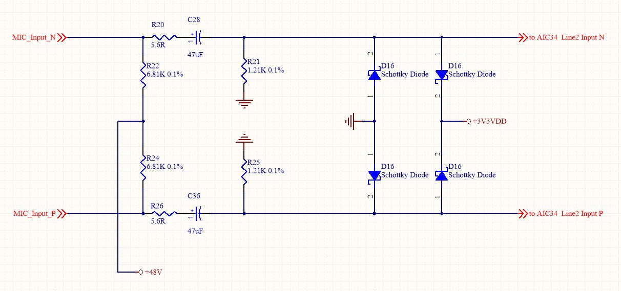
    A deeper analyzes shows that our input protection circuit with 2 Schottky diodes for each diff. input is causing my problem.

    It seems like the leakage current is causing a DC offset in the input circuitry of the AIC34.

    It also seems to me as when  this DC offset is amplified with a high PGA gain to a level above 0dB the channel gets muted.


    For a quick check I did just but two capacitors in front of the AIC34 input . With this modification the lager DC offset and my problem is gone.

     Can you recommend a better protection circuit for the inputs of the AIC34. The integrated protection is not sufficient for our 48V phantom powered MIC inputs.


    Thanks

    Thomas

  • Hi, Thomas,

    I suggest to take a look of the TLV320AIC34EVM schematic. You can find the suggested components connected to the inputs and to the outputs.

    Could you provide more information about the 48V phantom powered MIC inputs? It is important to respect the maximum ratings of the analog inputs in the TLV320AIC34. If your input signal is not in these ranges, you may damage the codec.

    Best regards,

    Luis Fernando Rodríguez S.

  • Hello Luis Fernando,


    I will attach the simplified schematics of our protection circuit with the schottky diodes.


    The input circuitry (BIAS voltage) of the AIC34 seems to be sensitive to the leakage current of the schottky diode bridge.

    Can you recommend a better circuitry to add a more robust protection (ESD absorb capability) to the AIC34 inputs without impacting the input BIAS voltage?


    Thanks

    Thomas

  • Hi, Thomas,

    Please take a look of the TPD1E10B09, TPD1E10B06 and TPD1E6B06. These are ESD protection devices that could help you with this issue. Additionally, you may take a look of the System-level ESD/EMI Protection Guide.  It mentions some devices that may avoid the ESD problems.

    I hope this helps you. If you still have questions or comments, please let me know.

    Best regards,

    Luis Fernando Rodríguez S.