This thread has been locked.

If you have a related question, please click the "Ask a related question" button in the top right corner. The newly created question will be automatically linked to this question.

Suitable DAC/Interface receive pairing to match PCM4201 with DIT4096 on the transmit side.

Other Parts Discussed in Thread: PCM4201, DIT4096, DIR9001, PCM5102, PCM5102A

I originally posted this question to Ti's support and was redirected to send it through their distributors. Said distributors failed to gain me a reply after weeks orf reminders. Ti then directed me to post it here on this forum so that their experts can deal with it. What a rigmarole! Anyway, here goes, in the hope that someone can give me an answer.

Problem:
I need to design a low chip count transmit/receive system for an audio signal using optical fibres. I'm considering using an ADC/DAC pairing at each end but don't want to have to use processors if I can avoid it. I hit on the idea of using your PCM4201 with DIT4096 for the transmit side (with suitable buffering and optical transmitter) but am not clear about what to use for the receive end. I'm hoping you can advise. A bonus would be if there was a way of adding a couple of logic signal bits but that's not mandatory as I can signal them using a high audio frequencies above the telephony band. Power is not an issue, BTW. Any ideas or suggestions? Thanks for your time

  • Hi Colin,

    I am sorry you had such a tough time with having to go back and forth to get some answers. Hopefully I can help you out. A good receiver that is hardware controlled for SPDIF over optical would be the DIR9001. This will take the SPDIF and turn it into PCM data. It will also clean up the jitter from the SPDIF clock. If you want digital audio out then you don't need anything else, if you would like analog out you might want to look at the PCM510XA series as they are hardware controlled DACs with different levels of performance.

    There are ways that you can encode data using the SPDIF user bits that could then be interpreted however you want on the other end. So you might want to look into the user bits available for the SPDIF.

    Justin
  • Hi Justin. Thanks for the suggestions. I am now planning to use PCM4201 -> DIT4096 -> DIR9001 -> PCM4201. Hardware mode. No Processor involved. I am trying to figure out how to inject user data bits. I have searched high and low for any proper applications notes for these four devices but can't find any. I've also fruitlessly spent some hours trying to find any relevant posts on the forum.
    I'd appreciate any help anyone can offer. I should explain that I am completely new to designing digital audio systems so it's a bit of a learning curve for me. The application is a bespoke telephony-over-fibre link in an industrial potentially hazardous environment. I could do with two user bits being switchable from external logic signals at one end to produce logic signals at the other.
  • HI Colin,

    As for the DIT4096, in hardware mode you have control over the User data bit on page 9 of the data sheet. These are controlled by pull ups or pull downs on the pins themselves for hardware mode. If you want access to more User data you will have to use software mode. The DIR9001 will then have those same pins as outputs for receiving the signal. The more extensive User data would come from the Cout and Uout pins as serial data synced with the clocks.

    Justin
  • Hi Justin,
    I have another question, if I may.
    I have a sequence of PCM4201 (ADC) --> DIT4096 (TX) --> DIR9001 (RX) --> PCM5102 (DAC).
    The signal path all works through to the output of the DIR9001 but the PCM5102 fails to give any output at all.
    Since the PCM4201 has a single audio channel whereas the PCM5102 has two (for stereo), I'm wondering if there is some incompatibility between these two devices. I can't find any information about this on forums or anywhere else so I'm hoping you at Ti can answer my query, please.
    FYI, I only need one audio channel.
    Kind regards, Colin.
  • Hi Colin,

    These parts should be compatible. They both communicate in PCM I2S interfaces, have you checked that the DIT is outputting valid SPDIF? Also can you try inputting a known good SPDIF signal into the DIR to see if the PCM5102 outputs audio? This signal chain should be valid, and the result will be that the PCM5102 will only output on the left channel.

    Justin
  • Thanks Justin. I don't have any other known good sources as you suggest so I'm stuck.

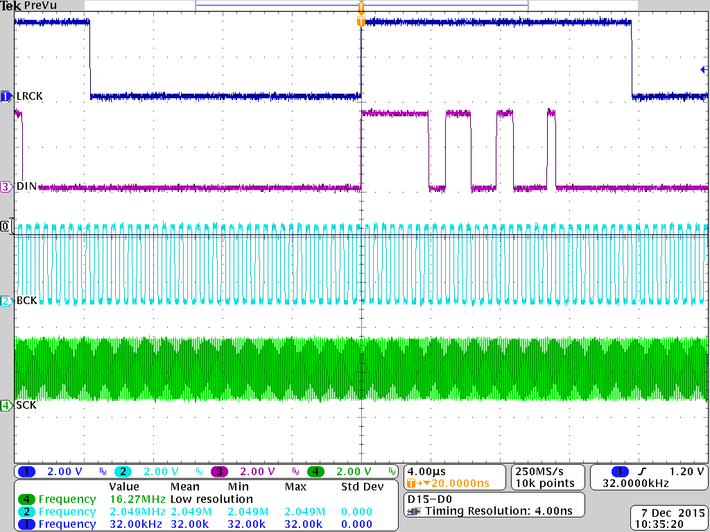
    May I ask you for your further input, please. I have checked and double-checked the SCK, BCK, LRCK and DIN signals being fed to the PCM5102. All look good with nice tight timings and clean waveforms.

    Likewise, I have double-checked the hardware settings such as FMT. All OK.

    I tried a new chip, in case the old one was defunct but to no avail. Still no audio output whatsoever.

    When I check the voltage on the charge pump pin  VNEG, it is zero. This appears to imply that the device is in shutdown, as far as I can see.

    Can you suggest anything else that would cause the device to stay shut down?

    I am using 24-bit MSB-first left-justified between TX and RX. The originatiing ADC (PCM4201) is set to 32kHz sampling and clocked at 512fs (16.348MHz).

  • Hi Colin,

    Clock errors, no clocks, and unpowered power rails will keep the part in power down. Is it possible for you to post the schematic of the PCM5102A on your board?

    Have you checked that all your power rails are where they should be?

    Justin
  • Hi Justin. Thanks for your continued support which is much appreciated since I am new to this digital audio stuff.
    Yes, I have checked all the rails, including the 1.8V core pin. Voltages well within spec and no nasties on them. The only line missing is the charge-pump-generated negative rail, as I mentioned before.
    I have a schematic and 'scoped waveforms I could post if only I could figure out how to do this. I can find no options on this thread page nor on my account profile. How and where do I post them?
  • Hi Colin,

    When posting a response there is a "Use rich formatting" option in the bottom right. Following that link will bring you to a page that has a utility bar with an add image or attach file options on it.

    Justin
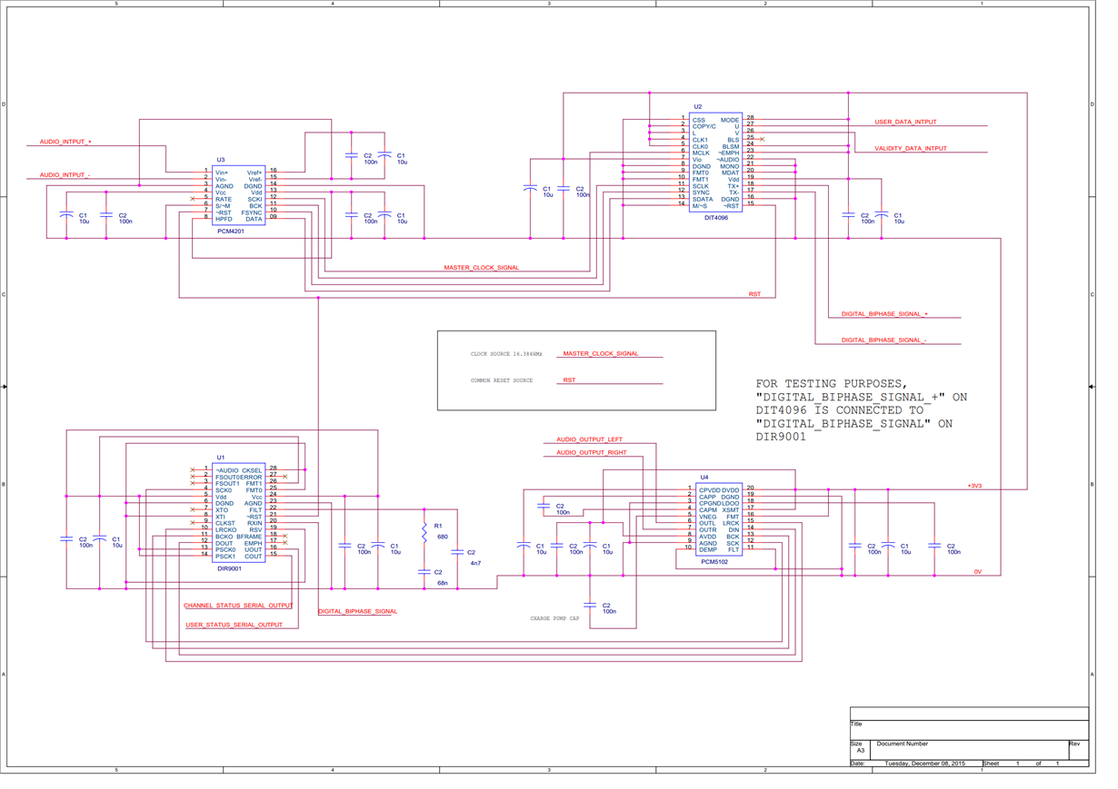
  • Ah! That's how it's done. Thanks. So I'm attaching the schematic plus a 'scope screenshot showing the waveforms reaching the PCM5102.

  • Just realised pin 1 (CAPVDD) needs to be connected to 3V3. I had thought it was just decoupling an internal connection. Applying 3V3 makes the charge-pumped Vneg spring to life so the chip is not powered down, after all. But I'm still not getting audio output so there's still a problem.
  • Hi Colin,

    Has there been any movement on this issue since your last post?

    Justin
  • Hi Justin,

    Sorry for late reply: I have been on leave. I've had no progress and have run out of ideas to try. The chip simply refuses to work. Probably me doing something silly but there's a limit to how many times you can double-check everything or ask colleagues to check. I've had to put this chip-set to one side and have taken delivery of some alternative chips. Thanks for your time, anyway.

    Colin.

  • Hi Colin,

    Sorry to hear that. Please feel free to come back with any additional questions you have, if you have time to take another look there is an EVM Users Guide you can compare your setup/PCB schematic to: www.ti.com/.../sbau108a.pdf

    Justin