This thread has been locked.

If you have a related question, please click the "Ask a related question" button in the top right corner. The newly created question will be automatically linked to this question.

Weird grounded input behaviour with TLV320AIC3254

Other Parts Discussed in Thread: TLV320AIC3254

Hi there,

I'm still working with the TLV320AIC3254 on a similar project,but I gave up the inverted inputs issue (original topic).

Indeed, I decided to use a single better microphone on only one input, avoiding the sum/difference issue. However, to have a quick overview, I first didn't modify the PF (you can read the config on the original topic) just to check if the new micro+amplifier were correct. They work ! But during these quick tests, I noticed a weird behaviour of my inputs and I would like to get your opinion/solution about it.

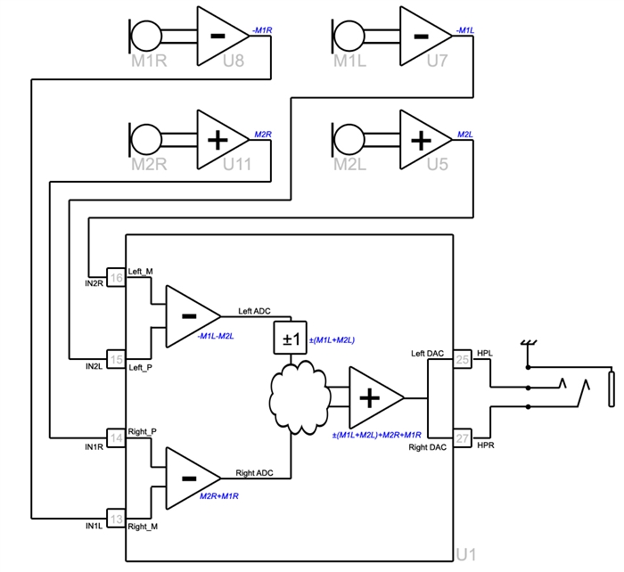
I plugged my preamp on IN1R and grounded the 3 other inputs. As the original program summed them all together (summed the 2 differential pairs, which were in fact the difference of 2 opposite signals each... anyway), I was supposed to get IN1R+IN1L+IN2R+IN2L on my output (HPR/L), and as inputs were all grounded except IN1R, I just was supposed to get IN1R+0+0+0. Right ?

Definitly not ! I got a weird silent output which cracks (like over clipping) when the sound becomes too loud or when blowing on the mic. I first thought about grounding issue or instability... But as this mic signal is used elsewhere on the board, I knew the signal was good and the ground didn't have such a huge weakness... And I finally found that when the 3 others input pins where let unplugged, my ouput was good as IN1R. Why !?

Why do you think grounding inputs can involve such a weird behaviour whereas letting them unplugged gives me the normal signal ?


Cheers !

  • I made a few other tests and the weird stuff is still there, but only concerns one input pin.

    First of all, here is a better synthetic view of the program in the codec:


    And this is what I found : I can ground one (doesn't matter which one) or both pins of the second pair, it works. However, grounding the second pin of the mic pair makes it not working. Weird isn't it ?
    Do you understand the behaviour of the codec inputs ?


    Just as a recall here is my codec setting:

    ;-----------------------------------------------------------------------------------
    ; Software Reset
    ;-----------------------------------------------------------------------------------
    reg[ 0][ 1] = 0x01 ; Initialize the device through software reset
    reg[254][ 0] = 0x0a ; Delay 10ms
    
    ;-----------------------------------------------------------------------------------
    ; Configure Power Supplies
    ;-----------------------------------------------------------------------------------
    %%if (%%prop(TargetBoard) == 2)
    ; AIC3254EVM-U specific configuration
    
    reg[ 1][ 2] = 0xa9 ; Power up AVDD LDO
    reg[ 1][ 1] = 0x08 ; Disable weak AVDD to DVDD connection
    reg[ 1][ 2] = 0xa1 ; Enable Master Analog Power Control, AVDD LDO Powered
    
    %%else
    ; AIC3254EVM-K specific configuration
    reg[ 1][ 1] = 0x08 ; Disable weak AVDD to DVDD connection
    reg[ 1][ 2] = 0x00 ; Enable Master Analog Power Control
    
    %%endif
    
    reg[ 1][ 71] = 0x32 ; Set the input power-up time to 3.1ms
    reg[ 1][123] = 0x01 ; Set REF charging time to 40ms (automatic)
    ; reg[254][0] = 0x28 ; Delay 40ms for REF to Power Up
    
    ;-----------------------------------------------------------------------------------
    ; Load miniDSP Code
    ;-----------------------------------------------------------------------------------
    PROGRAM_ADC ; miniDSP_A coefficients and instructions
    PROGRAM_DAC ; miniDSP_D coefficients and instructions
    
    ;-----------------------------------------------------------------------------------
    ; Signal Processing Settings
    ;-----------------------------------------------------------------------------------
    %%if (%%prop(SynchMode) == 1)
    ; SynchMode is enabled
    reg[ 0][ 60] = 0x80 ; DAC prog Mode: miniDSP_A and miniDSP_D ARE powered up together, miniDSP_A used for signal processing
    %%else
    ; SynchMode is disabled
    reg[ 0][ 60] = 0x00 ; DAC prog Mode: miniDSP_A and miniDSP_D NOT powered up together, miniDSP_A used for signal processing
    %%endif
    reg[ 0][ 61] = 0x00 ; Use miniDSP_A for signal processing
    
    %%if ("%%prop(FrameworkType)" == "AIC3254App8x4x")
    reg[ 0][ 17] = 0x08 ; 8x Interpolation
    reg[ 0][ 23] = 0x04 ; 4x Decimation
    %%endif
    
    %%if ("%%prop(FrameworkType)" == "AIC3254App4x2x")
    reg[ 0][ 17] = 0x04 ; 4x Interpolation
    reg[ 0][ 23] = 0x02 ; 2x Decimation
    %%endif
    
    %%if ("%%prop(FrameworkType)" == "AIC3254App2x1x")
    reg[ 0][ 17] = 0x02 ; 2x Interpolation
    reg[ 0][ 23] = 0x01 ; 1x Decimation
    %%endif
    
    IDAC = %%prop(miniDSP_D_Cycles)
    IADC = %%prop(miniDSP_A_Cycles)
    
    %%if (%%prop(miniDSP_A_Adaptive) == 1)
    reg[ 8][ 1] = 0x04 ; adaptive mode for ADC
    %%endif
    
    %%if (%%prop(miniDSP_D_Adaptive) == 1)
    reg[ 44][ 1] = 0x04 ; adaptive mode for DAC
    %%endif
    
    ;-----------------------------------------------------------------------------------
    ; Clock and Interface Configuration
    ;-----------------------------------------------------------------------------------
    ; USB Audio supports 8kHz to 48kHz sample rates
    ; An external audio interface is required for 88.2kHz to 192kHz sample rates
    ;-----------------------------------------------------------------------------------
    %%if (%%prop(SampleRate) == 176400 || %%prop(SampleRate) == 192000)
    reg[ 0][ 5] = 0x91 ; P=1, R=1, J=8
    reg[ 0][ 6] = 0x08 ; P=1, R=1, J=8
    reg[ 0][ 7] = 0x00 ; D=0000 (MSB)
    reg[ 0][ 8] = 0x00 ; D=0000 (LSB)
    reg[ 0][ 4] = 0x03 ; PLL_clkin = MCLK, codec_clkin = PLL_CLK, PLL on
    reg[ 0][ 12] = 0x88 ; MDAC = 8, divider powered on
    reg[ 0][ 13] = 0x00 ; DOSR = 32 (MSB)
    reg[ 0][ 14] = 0x20 ; DOSR = 32 (LSB)
    reg[ 0][ 18] = 0x02 ; NADC = 2, divider powered off
    reg[ 0][ 19] = 0x88 ; MADC = 8, divider powered on
    reg[ 0][ 20] = 0x20 ; AOSR = 32
    reg[ 0][ 11] = 0x82 ; NDAC = 2, divider powered on
    
    %%endif
    
    %%if (%%prop(SampleRate) == 88200 || %%prop(SampleRate) == 96000)
    reg[ 0][ 5] = 0x91 ; P=1, R=1, J=8
    reg[ 0][ 6] = 0x08 ; P=1, R=1, J=8
    reg[ 0][ 7] = 0x00 ; D=0000 (MSB)
    reg[ 0][ 8] = 0x00 ; D=0000 (LSB)
    reg[ 0][ 4] = 0x03 ; PLL_clkin = MCLK, codec_clkin = PLL_CLK, PLL on
    reg[ 0][ 12] = 0x88 ; MDAC = 8, divider powered on
    reg[ 0][ 13] = 0x00 ; DOSR = 64 (MSB)
    reg[ 0][ 14] = 0x40 ; DOSR = 64 (LSB)
    reg[ 0][ 18] = 0x02 ; NADC = 2, divider powered off
    reg[ 0][ 19] = 0x88 ; MADC = 8, divider powered on
    reg[ 0][ 20] = 0x40 ; AOSR = 64
    reg[ 0][ 11] = 0x82 ; NDAC = 2, divider powered on
    %%endif
    
    %%if (%%prop(SampleRate) == 44100 || %%prop(SampleRate) == 48000)
    reg[ 0][ 5] = 0x91 ; P=1, R=1, J=8
    reg[ 0][ 6] = 0x08 ; P=1, R=1, J=8
    reg[ 0][ 7] = 0x00 ; D=0000 (MSB)
    reg[ 0][ 8] = 0x00 ; D=0000 (LSB)
    reg[ 0][ 4] = 0x03 ; PLL_clkin = MCLK, codec_clkin = PLL_CLK, PLL on
    reg[ 0][ 12] = 0x88 ; MDAC = 8, divider powered on
    reg[ 0][ 13] = 0x00 ; DOSR = 128 (MSB)
    reg[ 0][ 14] = 0x80 ; DOSR = 128 (LSB)
    reg[ 0][ 18] = 0x02 ; NADC = 2, divider powered off
    reg[ 0][ 19] = 0x88 ; MADC = 8, divider powered on
    reg[ 0][ 20] = 0x80 ; AOSR = 128
    reg[ 0][ 11] = 0x82 ; NDAC = 2, divider powered on
    %%endif
    
    %%if (%%prop(SampleRate) == 32000)
    reg[ 0][ 5] = 0x91 ; P=1, R=1, J=8
    reg[ 0][ 6] = 0x08 ; P=1, R=1, J=8
    reg[ 0][ 7] = 0x00 ; D=0000 (MSB)
    reg[ 0][ 8] = 0x00 ; D=0000 (LSB)
    reg[ 0][ 4] = 0x03 ; PLL_clkin = MCLK, codec_clkin = PLL_CLK, PLL on
    reg[ 0][ 12] = 0x88 ; MDAC = 8, divider powered on
    reg[ 0][ 13] = 0x00 ; DOSR = 192 (MSB)
    reg[ 0][ 14] = 0xc0 ; DOSR = 192 (LSB)
    reg[ 0][ 18] = 0x02 ; NADC = 2, divider powered off
    reg[ 0][ 19] = 0x8c ; MADC = 12, divider powered on
    reg[ 0][ 20] = 0x80 ; AOSR = 128
    reg[ 0][ 11] = 0x82 ; NDAC = 2, divider powered on
    %%endif
    
    %%if (%%prop(SampleRate) == 22050 || %%prop(SampleRate) == 24000)
    reg[ 0][ 5] = 0x91 ; P=1, R=1, J=8
    reg[ 0][ 6] = 0x08 ; P=1, R=1, J=8
    reg[ 0][ 7] = 0x00 ; D=0000 (MSB)
    reg[ 0][ 8] = 0x00 ; D=0000 (LSB)
    reg[ 0][ 4] = 0x03 ; PLL_clkin = MCLK, codec_clkin = PLL_CLK, PLL on
    reg[ 0][ 12] = 0x88 ; MDAC = 8, divider powered on
    reg[ 0][ 13] = 0x01 ; DOSR = 256 (MSB)
    reg[ 0][ 14] = 0x00 ; DOSR = 256 (LSB)
    reg[ 0][ 18] = 0x02 ; NADC = 2, divider powered off
    reg[ 0][ 19] = 0x90 ; MADC = 16, divider powered on
    reg[ 0][ 20] = 0x80 ; AOSR = 128
    reg[ 0][ 11] = 0x82 ; NDAC = 2, divider powered on
    %%endif
    
    %%if (%%prop(SampleRate) == 16000)
    reg[ 0][ 5] = 0x91 ; P=1, R=1, J=24
    reg[ 0][ 6] = 0x18 ; P=1, R=1, J=24
    reg[ 0][ 7] = 0x00 ; D=0000 (MSB)
    reg[ 0][ 8] = 0x00 ; D=0000 (LSB)
    reg[ 0][ 4] = 0x03 ; PLL_clkin = MCLK, codec_clkin = PLL_CLK, PLL on
    reg[ 0][ 12] = 0x88 ; MDAC = 8, divider powered on
    reg[ 0][ 13] = 0x01 ; DOSR = 384 (MSB)
    reg[ 0][ 14] = 0x80 ; DOSR = 384 (LSB)
    reg[ 0][ 18] = 0x02 ; NADC = 2, divider powered off
    reg[ 0][ 19] = 0x98 ; MADC = 24, divider powered on
    reg[ 0][ 20] = 0x80 ; AOSR = 128
    reg[ 0][ 11] = 0x82 ; NDAC = 2, divider powered on
    %%endif
    
    %%if (%%prop(SampleRate) == 11025)
    reg[ 0][ 5] = 0x91 ; P=1, R=1, J=16
    reg[ 0][ 6] = 0x10 ; P=1, R=1, J=16
    reg[ 0][ 7] = 0x00 ; D=0000 (MSB)
    reg[ 0][ 8] = 0x00 ; D=0000 (LSB)
    reg[ 0][ 4] = 0x03 ; PLL_clkin = MCLK, codec_clkin = PLL_CLK, PLL on
    reg[ 0][ 12] = 0x88 ; MDAC = 8, divider powered on
    reg[ 0][ 13] = 0x02 ; DOSR = 512 (MSB)
    reg[ 0][ 14] = 0x00 ; DOSR = 512 (LSB)
    reg[ 0][ 18] = 0x02 ; NADC = 2, divider powered off
    reg[ 0][ 19] = 0xa0 ; MADC = 32, divider powered on
    reg[ 0][ 20] = 0x80 ; AOSR = 128
    reg[ 0][ 11] = 0x82 ; NDAC = 2, divider powered on
    %%endif
    
    %%if (%%prop(SampleRate) == 8000)
    reg[ 0][ 5] = 0x91 ; P=1, R=1, J=24
    reg[ 0][ 6] = 0x18 ; P=1, R=1, J=24
    reg[ 0][ 7] = 0x00 ; D=0000 (MSB)
    reg[ 0][ 8] = 0x00 ; D=0000 (LSB)
    reg[ 0][ 4] = 0x03 ; PLL_clkin = MCLK, codec_clkin = PLL_CLK, PLL on
    reg[ 0][ 12] = 0x88 ; MDAC = 8, divider powered on
    reg[ 0][ 13] = 0x03 ; DOSR = 768 (MSB)
    reg[ 0][ 14] = 0x00 ; DOSR = 768 (LSB)
    reg[ 0][ 18] = 0x02 ; NADC = 2, divider powered off
    reg[ 0][ 19] = 0xb0 ; MADC = 48, divider powered on
    reg[ 0][ 20] = 0x80 ; AOSR = 128
    reg[ 0][ 11] = 0x82 ; NDAC = 2, divider powered on
    %%endif
    
    reg[ 0][ 29] = 0x10 ; Loopback ADC out to DAC in
    reg[ 0][ 30] = 0x80 ; BCLK out is DAC CLK div by 128
    reg[ 0][ 33] = 0x02 ; DOUT output = Secondary Data Input (Loopback)
    reg[ 0][ 27] = 0x0C ; b0 = 0: DOUT will not be high impedance while Audio Interface is active
    
    
    ;-----------------------------------------------------------------------------------
    ; ADC Channel Configuration
    ;-----------------------------------------------------------------------------------
    reg[ 1][ 51] = 0x40 ; Mic Bias enabled, Source = Avdd, 1.25V
    ; reg[ 1][ 51] = 0x00 ; Mic Bias disabled


    ; reg[ 1][ 52] = 0x40 ; Route IN1L to LEFT_P with 10K input impedance
    reg[ 1][ 52] = 0x10 ; Route IN2L to LEFT_P with 10K input impedance
    ; reg[ 1][ 52] = 0x04 ; Route IN3L to LEFT_P with 10K input impedance
    ; reg[ 1][ 52] = 0x01 ; Route IN1R to LEFT_P with 10K input impedance
    
    ; reg[ 1][ 54] = 0x40 ; Route CM to LEFT_M with 10K input impedance
    reg[ 1][ 54] = 0x10 ; Route IN2R to LEFT_M with 10K input impedance
    ; reg[ 1][ 54] = 0x04 ; Route IN3R to LEFT_M with 10K input impedance
    ; reg[ 1][ 54] = 0x01 ; Route CM to LEFT_M with 10K input impedance
    
    reg[ 1][ 55] = 0x40 ; Route IN1R to RIGHT_P with 10K input impedance
    ; reg[ 1][ 55] = 0x10 ; Route IN2R to RIGHT_P with 10K input impedance
    ; reg[ 1][ 55] = 0x04 ; Route IN3R to RIGHT_P with 10K input impedance
    ; reg[ 1][ 55] = 0x01 ; Route IN2R to RIGHT_P with 10K input impedance
    
    ; reg[ 1][ 57] = 0x40 ; Route CM to RIGHT_M with 10K input impedance
    reg[ 1][ 57] = 0x10 ; Route IN1L to RIGHT_M with 10K input impedance
    ; reg[ 1][ 57] = 0x04 ; Route IN3L to RIGHT_M with 10K input impedance
    ; reg[ 1][ 57] = 0x01 ; Route CM to RIGHT_M with 10K input impedance


    reg[ 1][ 59] = 48 ; Enable MicPGA_L Gain Control, 20dB
    reg[ 1][ 60] = 48 ; Enable MicPGA_R Gain Control, 20dB
    reg[ 0][ 81] = 0xc0 ; Power up LADC/RADC
    reg[ 0][ 82] = 0x00 ; Unmute LADC/RADC
    
    ;-----------------------------------------------------------------------------------
    ; DAC Channel Configuration
    ;-----------------------------------------------------------------------------------
    reg[ 1][ 20] = 0x25 ; De-pop: 5 time constants, 6k resistance
    reg[ 1][ 12] = 0x08 ; Route LDAC to HPL
    reg[ 1][ 13] = 0x08 ; Route RDAC to HPR
    reg[ 1][ 14] = 0x08 ; Route LDAC to LOL
    reg[ 1][ 15] = 0x08 ; Route LDAC to LOR
    reg[ 0][ 63] = 0xd4 ; Power up LDAC/RDAC w/ soft stepping
    reg[ 1][ 16] = 0x00 ; Unmute HPL driver, 0dB Gain
    reg[ 1][ 17] = 0x00 ; Unmute HPR driver, 0dB Gain
    reg[ 1][ 18] = 0x00 ; Unmute LOL driver, 0dB Gain
    reg[ 1][ 19] = 0x00 ; Unmute LOR driver, 0dB Gain
    reg[ 1][ 9] = 0x3c ; Power up HPL/HPR and LOL/LOR drivers
    reg[ 0][ 64] = 0x00 ; Unmute LDAC/RDAC

  • HI Maxime,

    If you configure the inputs as differential it will subtract + and - terminals including the DC component. For this reason, you cannot connect one of the pins directly to ground because this will create a huge DC offset at the ADC output. You always need to couple the input with a capacitor (as explained in pages 13 and 14 of this app note www.ti.com/.../slaa404).

    If you connect in single-ended mode, the M terminal of the MicPGA must be connected to CM. For example, if you connect two inputs to MicPGA_P using internal 10k-ohm resistors for each, then you need to connect the internal CM1x (10k) and CM2x (10k) to MicPGA_M.

    For differential mode, there is no need to connect CM to the MicPGA_M.

    Single Ended Example (must be AC-coupled with a capacitor):

    IN1_L > 10k > MicPGA_LP
    IN2_L > 10k > MicPGA_LP
    CM1_L > 10k > MicPGA_LM
    CM2_L > 10k > MicPGA_LM

    IN1_R > 10k > MicPGA_RP
    IN2_R > 10k > MicPGA_RP
    CM1_R > 10k > MicPGA_RM
    CM2_R > 10k > MicPGA_RM

    Differential Example (must be AC-coupled with a capacitor):

    IN1_L > 10k > MicPGA_LP
    IN2_R > 10k > MicPGA_LP

    IN1_R > 10k > MicPGA_RP
    IN2_L > 10k > MicPGA_RP

    Regards,

    J-

  • Thanks J- !

    However, I'm not sure about the DC difference, because my input is sure coupled with a cap before feeding to the codec (not highlighted on previous schematics). So none of my inputs has a DC voltage at this point. Unless the internal offset I kept involves such a difference... but in this case it is symetrically applied then it shouldn't make a difference, should it ?

    => reg[ 1][ 51] = 0x40 ; Mic Bias enabled, Source = Avdd, 1.25V

    Anyway, I'll use your advice with single-ended mode. In my case, I only have one single-ended mono input on IN1R so : IN1R > 10KO > MicPGARP and CM1R > 10KO > MICPGARM. Is it enough ? What should I do with other pins to avoid similar issues ?

    For better understanding, see my new schematics (forgive the miss of pull-down resistor on jack mic pin,it's a WIP), there is a coupling cap. Just imagine that this schematics comes up with the previous  block diagram regarding the codec's program with 3 other inputs grounded:

  • I just found something about  floating inputs in p1-reg58 (don't know what "weak" means in this case).

    Do you think I should use it to kill my not used inputs ?

  • I tried another config of codec inputs, but it still doesn't work.

    When IN1L pin is grounded or floating, it doesn't work. It works onloy if IN1L and IN1R are short-circtuit.

    This is my new config, acording to what you advised me to do, I only routed one micPGA with IN1R (coupled mic) on positive input and CM1R on negative input.

        {  0,0x01},
    //			# reg[  1][ 51] = 0x40	; Mic Bias enabled, Source = Avdd, 1.25V
        { 51,0x40},
    //			# reg[  1][ 52] = 0x00	; L_micPGA_P not routed
        { 52,0x00},
    //			# reg[  1][ 54] = 0x00	; L_micPGA_N not routed
        { 54,0x00},
    //			# reg[  1][ 55] = 0x40	; IN1R > 10k > R_micPGA_P
        { 55,0x40},
    //			# reg[  1][ 57] = 0x40	; CM1R > 10k > R_micPGA_N
        { 57,0x40},
    //			# reg[  1][ 59] = 0x80	; L_micPGA Gain Control disabled (0dB)
        { 59,0x80},
    //			# reg[  1][ 60] = 0x30	; R_micPGA Gain Control enabled, 24dB
        { 60,0x30},

    BTW, this is the config in phone mode (this one works, whatever IN1L is routed to) :

    //			# reg[  1][ 51] = 0x40	; Mic Bias enabled, Source = Avdd, 1.25V
        { 51,0x40},
    //			# reg[  1][ 52] = 0x04	; IN3L > 10k > L_micPGA_P
        { 52,0x04},
    //			# reg[  1][ 54] = 0x40	; CM1L > 10k > L_micPGA_N
        { 54,0x40},
    //			# reg[  1][ 55] = 0x04	; IN3R > 10k > R_micPGA_P
        { 55,0x04},
    //			# reg[  1][ 57] = 0x40	; CM1R > 10k > R_micPGA_N
        { 57,0x40},
    // 			# reg[  1][ 59] = 0x30	; Enable MicPGA_L Gain Control, 24dB
        { 59,0x30},		
    //			# reg[  1][ 60] = 0x30	; Enable MicPGA_R Gain Control, 24dB
        { 60,0x30},

  • The weak setting basically pulls the input to common mode (0.9V or 0.75V) even if the input stage is powered off. This is to reduce pop.
  • The 10k IN1R and 10k to CM connection you mentioned should work ok. Whenever you are not using an input pin, simply don't connect it to MicPGA_P. Whenever you need an input, connect it to MicPGA_P (e.g. 10k resistor) and connect CM with same resistor value to MicPGA_M.