This thread has been locked.

If you have a related question, please click the "Ask a related question" button in the top right corner. The newly created question will be automatically linked to this question.

PCM3168 Single-ended

Other Parts Discussed in Thread: PCM3168

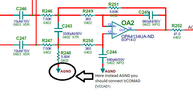
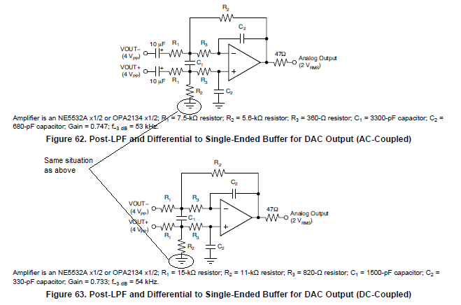
There is a bug in a documentation for PCM3168 and in User's Guide for motherboard for PCM3168 . How this circuit converts differential signal to single-ended? You should add some DC on non-inverted input, if not signal after conversion has reference voltage on AGND and negative part of the signal is cutting off.

This is a part of User's Guide for motherboard for PCM3168:

This is a part of PCM3168 datasheet:

Could you explain this strange situation?

  • Hi,

    The PCM3168 board has a +/-15 V supply for the opamps, so the output can be centered around AGND, without clipping. If you are using a single supply positive voltage, then you would need to bias the output to midrail.

    Justin
  • Hi Justin,


    "The PCM3168 board has a +/-15 V supply for the opamps, so the output can be centered around AGND, without clipping" this is simply not true. See this part of circuit:

    Where you see +/-15 V supply?pcm3168a_motherboard.pdf

  • My mistake. I was referencing another board. You are correct that the single ended output will be incorrect as the op amp will be clipping on the negative swing. The board allows for the differential output to go directly to the output connector. If you want to use the single ended output, you will need to add a negative supply for the opamp.

    If you use a positive and negative supply then you do not need to bias in the inputs. The data sheet references are with the use of a dual supply.

    Justin
  • Justin Bohr said:
    If you want to use the single ended output, you will need to add a negative supply for the opamp.

    How? This motherboard has fixed connection op amp supply to asymmetrical voltage. This is simply huge bug on PCB and it comes straight from datasheet. Few years ago I had sad surprise with DRV8432 - in datasheet first pin is show in two different places, moreover ESD protection of DRV8432 is terrible.

    Thanks for your answers Justin

    Pawel

  • Hi Pawel,

    You are correct that the board is not set up correctly for the single ended output. To fix this on your specific board you would have to find a way to disconnect the op amps negative supply pin from ground and blue wire a negative supply to it. The differential outputs that go to the connector can still be used.

    Justin
  • Justin,

    It is not solution for my problem. I have my own PCB with positive supply 5 V and negative GND (single supply), I connected VCOMAD pin as above. Does it is good approach? Output is connected to TDA8551 and everything seems to be good. TDA8551 has Vref = Vp/2 = 2,5 V and VCOMAD = 2,5 V so signal on the output is such as I expected.

    Justin you are generating so many answers but you not help me at all. Can you finally refer to my solution?

    Paweł

  • Hi Pawel,

    If you are looking for confirmation that adding Vcom to the point highlighted node, then yes I believe that is the right change to make is so the input and output will be biased at Vcom.

    Justin
  • Hi Justin,

    Thanks for your help.

    Paweł