This thread has been locked.

If you have a related question, please click the "Ask a related question" button in the top right corner. The newly created question will be automatically linked to this question.

TLV320AIC3204 - Question about Common Mode voltage

Other Parts Discussed in Thread: TLV320AIC3204

I'm working on a project using a TLV320AIC3204 CODEC and single ended microphone. The mic is a standard Electret type, and has a bias voltage applied by the MICBIAS output pin on the codec. The microphone signal passes through a 0.47uF coupling capacitor before entering the IN1_L pin on the the codec. The converted digital signal is read by a microcontroller and stored in a file. When I open the file in audio analysis software and "zoom in" on the graphically represented waveform, I see a small DC offset (i.e. the waveform is shifted above the zero line). I'd like to remove this offset, and I believe it's coming from the codecs common mode voltage.

I've set the common mode voltage to 0.9V to get the greatest dynamic range, and I notice the offset I'm seeing in the output is right at 0.9V

My first question: Is this expected behavior? And my second question: If this is expected behavior, is there a way to remove this offset in the output?

Thanks in advance for your help,

-Rob

  • Hi, Rob,

    You're right. Actually, this common mode voltage is generated when the 0.47 uF is connected to the analog input. This voltage is used to accept the negative values at the input. So, if you are looking to remove this DC offset, I would suggest to configure a biquad filter as a High-Pass Filter. The ADC processing blocks can be configured to define a high-pass filter.

    Also, I suggest to use our TI Biquad calculator tool to get the filter coefficients: www.ti.com/.../COEFFICIENT-CALC

    Please let me know if you have questions or comments.

    Best regards,
    Luis Fernando Rodríguez S.
  • Hi Luis,

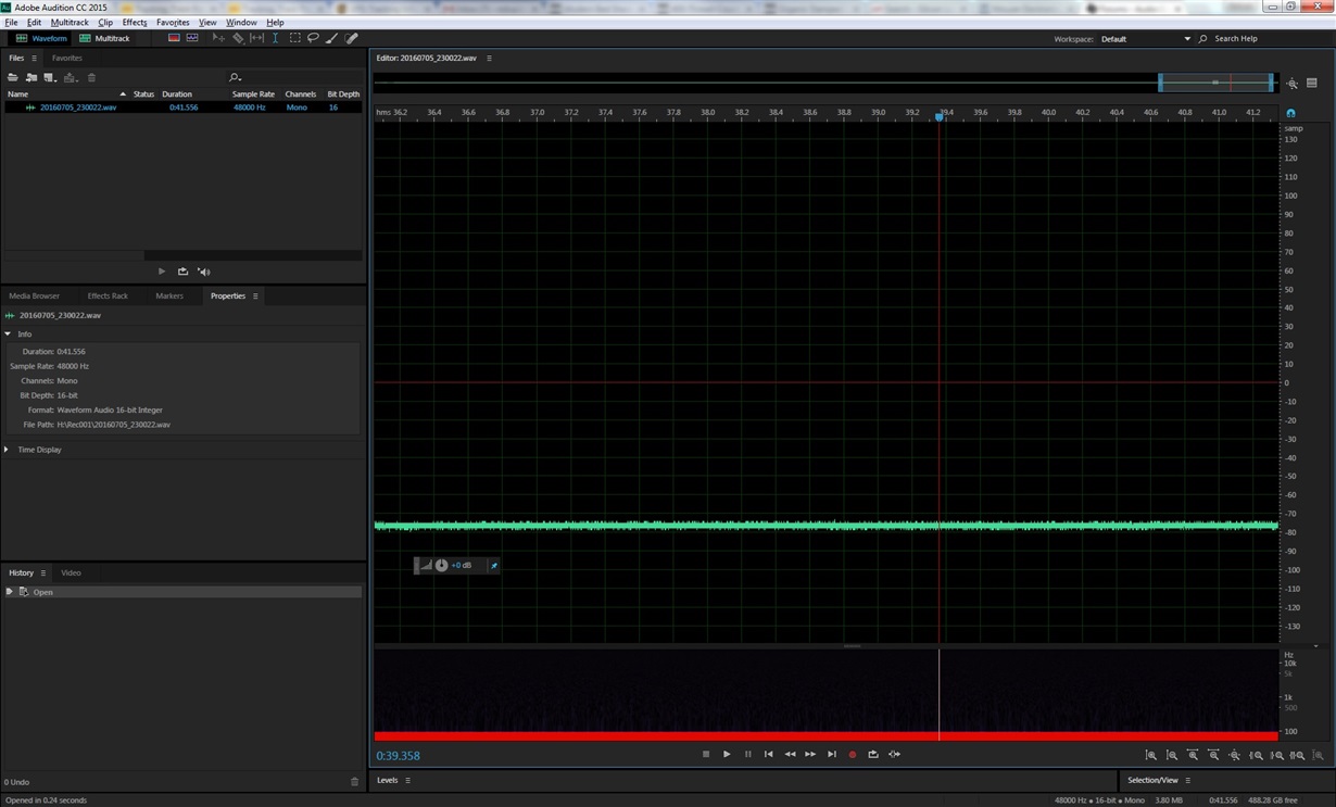
    Thank you very much for your reply and confirming my suspicion about the DC offset voltage. There is still one thing I don't completely understand, and I will try to explain by referencing the attached screenshot of an audio snippet recorded using my application circuit.

    If you look at the green signal you will notice that the majority of the samples fall below the red zero reference line. This would indicate the common mode DC offset of 0.9V (as already discussed). The thing I don't understand is why some samples fall above the red reference line. Conceptually speaking, shouldn't all audio samples fall between 0 and 1.8V (the analog supply voltage)? I'm sure there is a simple explanation here that I'm just not aware of

    Thanks again,

    Rob

  • Hi, Rob,

    Excuse me, could you provide the codec schematic and the register configuration, please? It is to have a better approach to this issue.

    Thank you.

    Best regards,
    Luis Fernando Rodríguez S.
  • And here's my codec configuration:

      //**************************************************************************
      //** Page Zero *************************************************************
    
      // Select codec page 0
      aTxBuffer[0] = 0; //Register
      aTxBuffer[1] = 0; //Value
      HAL_I2C_Master_Transmit(i2c1, (uint16_t)CODEC_I2C_ADDRESS, (uint8_t*)aTxBuffer, (uint16_t)2, 10000);
      
      // Clock Setting Register 1, Multiplexers
      aTxBuffer[0] = 0x04; //Register
      aTxBuffer[1] = 0x03;//Value
      HAL_I2C_Master_Transmit(i2c1, (uint16_t)CODEC_I2C_ADDRESS, (uint8_t*)aTxBuffer, (uint16_t)2, 10000);
    
      // Clock Setting Register 2, PLL P and R Values
      aTxBuffer[0] = 0x05; //Register
      //aTxBuffer[1] = PLLPR;//0xA1;//Value
      aTxBuffer[1] = SwiftHandle->CODEC_CONFIG.Codec_PLL_PR;
      HAL_I2C_Master_Transmit(i2c1, (uint16_t)CODEC_I2C_ADDRESS, (uint8_t*)aTxBuffer, (uint16_t)2, 10000);
      
      // Clock Setting Register 3, PLL J Values
      aTxBuffer[0] = 0x06; //Register
      //aTxBuffer[1] = PLLJ;//0x06;//Value
      aTxBuffer[1] = SwiftHandle->CODEC_CONFIG.Codec_PLL_J;
      HAL_I2C_Master_Transmit(i2c1, (uint16_t)CODEC_I2C_ADDRESS, (uint8_t*)aTxBuffer, (uint16_t)2, 10000);
      
      // Clock Setting Register 4, PLL D Values
      aTxBuffer[0] = 0x07; //Register
      //aTxBuffer[1] = PLLD_MSB;//0x05;//Value
      aTxBuffer[1] = SwiftHandle->CODEC_CONFIG.Codec_PLL_D_MSB;
      HAL_I2C_Master_Transmit(i2c1, (uint16_t)CODEC_I2C_ADDRESS, (uint8_t*)aTxBuffer, (uint16_t)2, 10000);
      
      // Clock Setting Register 5, PLL D Values
      aTxBuffer[0] = 0x08; //Register
      //aTxBuffer[1] = PLLD_LSB;//0xA0;//Value
      aTxBuffer[1] = SwiftHandle->CODEC_CONFIG.Codec_PLL_D_LSB;
      HAL_I2C_Master_Transmit(i2c1, (uint16_t)CODEC_I2C_ADDRESS, (uint8_t*)aTxBuffer, (uint16_t)2, 10000);
      
      // Clock Setting Register 8, NADC Values
      aTxBuffer[0] = 0x12; //Register (0x12 = 18)
      //aTxBuffer[1] = (NADC | 128);//0x83; //Value
      aTxBuffer[1] = (SwiftHandle->CODEC_CONFIG.Codec_NADC | 128);
      HAL_I2C_Master_Transmit(i2c1, (uint16_t)CODEC_I2C_ADDRESS, (uint8_t*)aTxBuffer, (uint16_t)2, 10000);
    
      // Clock Setting Register 9, MADC Values
      aTxBuffer[0] = 0x13; //Register (0x13 = 19)
      //aTxBuffer[1] = (MADC | 128); //Value
      aTxBuffer[1] = (SwiftHandle->CODEC_CONFIG.Codec_MADC | 128);
      HAL_I2C_Master_Transmit(i2c1, (uint16_t)CODEC_I2C_ADDRESS, (uint8_t*)aTxBuffer, (uint16_t)2, 10000);
    
      // ADC Oversampling (AOSR) Register
      aTxBuffer[0] = 0x14; //Register (0x14 = 20)
      //aTxBuffer[1] = AOSR; //Value
      aTxBuffer[1] = SwiftHandle->CODEC_CONFIG.Codec_AOSR;
      HAL_I2C_Master_Transmit(i2c1, (uint16_t)CODEC_I2C_ADDRESS, (uint8_t*)aTxBuffer, (uint16_t)2, 10000);
    
      // Audio Interface Setting Register 1
      aTxBuffer[0] = 0x1B; //Register
      aTxBuffer[1] = 0x4C; //Value
      HAL_I2C_Master_Transmit(i2c1, (uint16_t)CODEC_I2C_ADDRESS, (uint8_t*)aTxBuffer, (uint16_t)2, 10000);
    
      // Audio Interface Setting Register 2, Data offset setting
      aTxBuffer[0] = 0x1C; //Register
      aTxBuffer[1] = 0x01; //Value
      HAL_I2C_Master_Transmit(i2c1, (uint16_t)CODEC_I2C_ADDRESS, (uint8_t*)aTxBuffer, (uint16_t)2, 10000);
    
      // Audio Interface Setting Register 3
      aTxBuffer[0] = 0x1D; //Register
      aTxBuffer[1] = 0x02; //Value
      HAL_I2C_Master_Transmit(i2c1, (uint16_t)CODEC_I2C_ADDRESS, (uint8_t*)aTxBuffer, (uint16_t)2, 10000);
    
      // Clock Setting Register 11, BCLK N Divider
      aTxBuffer[0] = 0x1E; //Register (0x1E = 30)
      //aTxBuffer[1] = (BDIV | 128); //Value
      aTxBuffer[1] = (SwiftHandle->CODEC_CONFIG.Codec_BDIV | 128);
      HAL_I2C_Master_Transmit(i2c1, (uint16_t)CODEC_I2C_ADDRESS, (uint8_t*)aTxBuffer, (uint16_t)2, 10000);
    
      // Audio Interface Setting Register 6
      aTxBuffer[0] = 0x21; //Register (0x21 = 33)
      aTxBuffer[1] = 0x10; //Value
      HAL_I2C_Master_Transmit(i2c1, (uint16_t)CODEC_I2C_ADDRESS, (uint8_t*)aTxBuffer, (uint16_t)2, 10000);
    
      // ADC Flag Register
      //aTxBuffer[0] = 0x24; //Register
      //aTxBuffer[1] = 0xC8; //Value
      //HAL_I2C_Master_Transmit(&i2c1, (uint16_t)CODEC_I2C_ADDRESS, (uint8_t*)aTxBuffer, (uint16_t)2, 10000);
    
      // Sticky Flag Register 1
      //aTxBuffer[0] = 0x2A; //Register
      //aTxBuffer[1] = 0x0A; //Value
      //HAL_I2C_Master_Transmit(&i2c1, (uint16_t)CODEC_I2C_ADDRESS, (uint8_t*)aTxBuffer, (uint16_t)2, 10000);
    
      // ADC Signal Processing Block Control Register
      aTxBuffer[0] = 0x3D; //Register (0x3D = 61)
      //aTxBuffer[1] = PRB; //Value
      aTxBuffer[1] = SwiftHandle->CODEC_CONFIG.Codec_PRB;
      HAL_I2C_Master_Transmit(i2c1, (uint16_t)CODEC_I2C_ADDRESS, (uint8_t*)aTxBuffer, (uint16_t)2, 10000);
    
      //**************************************************************************
      //** Page One **************************************************************
      //
    
      // Page Select Register
      aTxBuffer[0] = 0x00; //Register
      aTxBuffer[1] = 0x01; //Value
      HAL_I2C_Master_Transmit(i2c1, (uint16_t)CODEC_I2C_ADDRESS, (uint8_t*)aTxBuffer, (uint16_t)2, 10000);
    
      // Power Configuration Register - Disabled weak connection of AVDD with DVDD
      aTxBuffer[0] = 0x01; //Register
      aTxBuffer[1] = 0x08; //Value
      HAL_I2C_Master_Transmit(i2c1, (uint16_t)CODEC_I2C_ADDRESS, (uint8_t*)aTxBuffer, (uint16_t)2, 10000);
    
      // LDO Control Register
      aTxBuffer[0] = 0x02; //Register
      aTxBuffer[1] = 0xA1; //Value
      HAL_I2C_Master_Transmit(i2c1, (uint16_t)CODEC_I2C_ADDRESS, (uint8_t*)aTxBuffer, (uint16_t)2, 10000);
    
      // MICBIAS Configuration Register
      aTxBuffer[0] = 0x33; //Register
      aTxBuffer[1] = 0x68; //Value
      HAL_I2C_Master_Transmit(i2c1, (uint16_t)CODEC_I2C_ADDRESS, (uint8_t*)aTxBuffer, (uint16_t)2, 10000);
    
      // Left MICPGA Positive Terminal Input Routing Configuration Register
      aTxBuffer[0] = 0x34; //Register
      aTxBuffer[1] = 0x40; //Value
      HAL_I2C_Master_Transmit(i2c1, (uint16_t)CODEC_I2C_ADDRESS, (uint8_t*)aTxBuffer, (uint16_t)2, 10000);
    
      // Left MICPGA Negative Terminal Input Routing Configuration Register
      aTxBuffer[0] = 0x36; //Register
      aTxBuffer[1] = 0x40; //Value
      HAL_I2C_Master_Transmit(i2c1, (uint16_t)CODEC_I2C_ADDRESS, (uint8_t*)aTxBuffer, (uint16_t)2, 10000);
    
      // Floating Input Configuration Register
      aTxBuffer[0] = 0x3A; //Register
      aTxBuffer[1] = 0x80; //Value
      HAL_I2C_Master_Transmit(i2c1, (uint16_t)CODEC_I2C_ADDRESS, (uint8_t*)aTxBuffer, (uint16_t)2, 10000);
    
      // Left MICPGA Volume Control Register
      aTxBuffer[0] = 0x3B; //Register (0x3B = 59)
      //aTxBuffer[1] = GAIN; //Value
      aTxBuffer[1] = SwiftHandle->CODEC_CONFIG.Codec_GAIN;
      HAL_I2C_Master_Transmit(i2c1, (uint16_t)CODEC_I2C_ADDRESS, (uint8_t*)aTxBuffer, (uint16_t)2, 10000);
    
      // ADC Analog Volume Control Flag Register
      //aTxBuffer[0] = 0x3E; //Register
      //aTxBuffer[1] = 0x03; //Value
      //HAL_I2C_Master_Transmit(&i2c1, (uint16_t)CODEC_I2C_ADDRESS, (uint8_t*)aTxBuffer, (uint16_t)2, 10000);
    
      //**************************************************************************
      //** Page Zero *************************************************************
    
      // Select codec page 0
      aTxBuffer[0] = 0; //Register
      aTxBuffer[1] = 0; //Value
      HAL_I2C_Master_Transmit(i2c1, (uint16_t)CODEC_I2C_ADDRESS, (uint8_t*)aTxBuffer, (uint16_t)2, 10000);
    
      // ADC Channel Setup Register
      aTxBuffer[0] = 0x51; //Register
      aTxBuffer[1] = 0x80; //Value
      HAL_I2C_Master_Transmit(i2c1, (uint16_t)CODEC_I2C_ADDRESS, (uint8_t*)aTxBuffer, (uint16_t)2, 10000);
    
      // ADC Fine Gain Adjust Register
      aTxBuffer[0] = 0x52; //Register
      aTxBuffer[1] = 0x08; //Value
      HAL_I2C_Master_Transmit(i2c1, (uint16_t)CODEC_I2C_ADDRESS, (uint8_t*)aTxBuffer, (uint16_t)2, 10000);

  • By the way the zero ohm resistors R11 and R16 are not populated. They're jumpers to ground the analog input in case there's no microphone on that channel
  • Hi, Robert,

    I apologize for the late response.

    I already reviewed the schematic and the register configuration. The schematic is all in order. Regarding the register configuration, could you give details about the data offset that you're using? Is it necessary for your application?

    Additionally, is it possible to provide a screenshot when all the analog inputs are tied to GND, please?

    Thank you.

    Best regards,
    Luis Fernando Rodríguez S.
  • Hi Luis,

    So I've been messing around with the different configuration settings on both the CODEC and the I2S port on my microcontroller. I wanted to be sure the offset wasnt due to misreading the audio sample or bits being shifted. I am fairly confident that I’ve confirmed that everything is as it should be.

    The microcontroller I’m using is the STM32F407 from ST. It has an audio bus interface that supports various audio formats. The CODEC’s audio bus is the master and the Microcontroller is the slave. I set the CODEC’s I2S port to operate in DSP mode, and the microcontroller is set to “PCM Standard with Short Frame” with 16-bit data on a 32-bit frame. I had to set the microcontrollers I2S port up like this because of the way it handles mono audio data (my application uses mono audio only).

    You asked if the data offset is necessary. The answer is yes, because the microcontroller is expecting the MSB of the audio word to transition on the falling edge of the Word Clock.

    Being that the CODEC is the master, all audio bus signals are outputs on the CODEC (BCLK, WCLK, DOUT). The master clock is of course an input, and is set to 2MHz

    I can view the audio bus signals on my oscilloscope and verify that the clock polarity is as expected, the word length is correct, and I can even read audio sample values from the scope and verify that they’ve been read into the microcontroller correctly. In the attached scope screenshot, the blue channel is data, green is clock, and yellow is audio frame

    Finally, I did as you requested and tied the analog input to ground. The 0.47uF decoupling capacitor is still present at IN1_L (the input I’m using), but the far side of this capacitor is now grounded. I’m still seeing the reported offset in the recording. Please see the attached screenshot of the resulting audio recording with the CODEC input grounded 

    Thanks,

    Rob

  • Hi Luis,
    Any further information on this issue?

    Thanks,
    Rob
  • Hi, Rob,

    This could be related with the PLL coefficient values. You mentioned that the master clock is configured at 2MHz. However, I noticed that you're configuring the PLL with D ≠ 0. PLL section of reference guide explains the necessary conditions of the PLL values. Could you adjust your PLL values to ensure that it is in the correct range?

    Please let me know if you have more questions or comments.

    Best regards,
    Luis Fernando Rodríguez S.

  • Hi Luis,
    Yes, I did overlook that requirement. Thanks for noticing that my PLL D value was not equal to zero. I've now edited my code and set both D values to zero (msb and lsb) in registers 7 and 8 on page zero. After making the changes I ran several test recordings, but was surprised to see that this change had little effect other than changing the sample rate slightly. I kept everything else the same in my codec configuration, including the 2MHz master clock frequency. Sadly the DC offset that I originally reported did not change at all