This thread has been locked.

If you have a related question, please click the "Ask a related question" button in the top right corner. The newly created question will be automatically linked to this question.

TLV320AIC320 Analog Input Configuration

Other Parts Discussed in Thread: TLV320AIC3204

Hi,

We are using TLV320AIC3204 (CODEC) in our design, to interface MIC's differential output(analog) to the ports IN2L -MIC positive and IN2R- MIC negative output.

We would like to know the software level register setting for configuring IN2 port to accept differential signals.

Kindly share us the example source code for differential Analog input configuration.

Thank you for your support.

Best Regards,

Hema Sundar

  • Hello, Hema,

    Welcome to E2E and thank you for your interest in our products!

    Please take a look at the attached script. It contains an configuration example to route the differential IN2L/R lines to the left ADC.

    Differential_Mic_IN2.txt
    ###############################################
    # IN2L/R is are routed differentially to the
    # LADC.
    ###############################################
    
    ###############################################
    # Software Reset
    ###############################################
    #
    # Select Page 0
    w 30 00 00
    #
    # Initialize the device through software reset
    w 30 01 01
    #
    ###############################################
    
    ###############################################
    # Clock Settings
    # ---------------------------------------------
    # The codec receives: MCLK = 11.2896 MHz,
    # BLCK = 2.8224 MHz, WCLK = 44.1 kHz
    ###############################################
    #
    # Select Page 0
    w 30 00 00
    #
    # NADC = 1, MADC = 2
    w 30 12 81 82
    #
    ###############################################
    
    ###############################################
    # Signal Processing Settings
    ###############################################
    #
    # Select Page 0
    w 30 00 00
    #
    # Set the ADC Mode to PRB_P1
    w 30 3d 01
    #
    ###############################################
    
    ###############################################
    # Initialize Codec
    ###############################################
    #
    # Select Page 1
    w 30 00 01
    #
    # Disable weak AVDD in presence of external
    # AVDD supply
    w 30 01 08
    #
    # Enable Master Analog Power Control
    w 30 02 00
    #
    # Select ADC PTM_R4
    w 30 3d 00
    #
    # Set the input powerup time to 3.1ms (for ADC)
    w 30 47 32
    #
    # Set the REF charging time to 40ms
    w 30 7b 01
    #
    ###############################################
    
    ###############################################
    # Recording Setup
    ###############################################
    #
    # Select Page 1
    w 30 00 01
    #
    # Powerup MIC BIAS
    w 30 33 40
    #
    # Route IN2L to LEFT_P with 10K input impedance
    w 30 34 10
    #
    # Route IN2R to LEFT_M with 10K input impedance
    w 30 36 10
    #
    # Unmute Left MICPGA
    w 30 3b 00
    #
    # Unmute Right MICPGA
    w 30 3c 00
    #
    # Select Page 0
    w 30 00 00
    #
    # Power up LADC/RADC
    w 30 51 c0
    #
    # Unmute LADC/RADC
    w 30 52 00
    #
    ###############################################

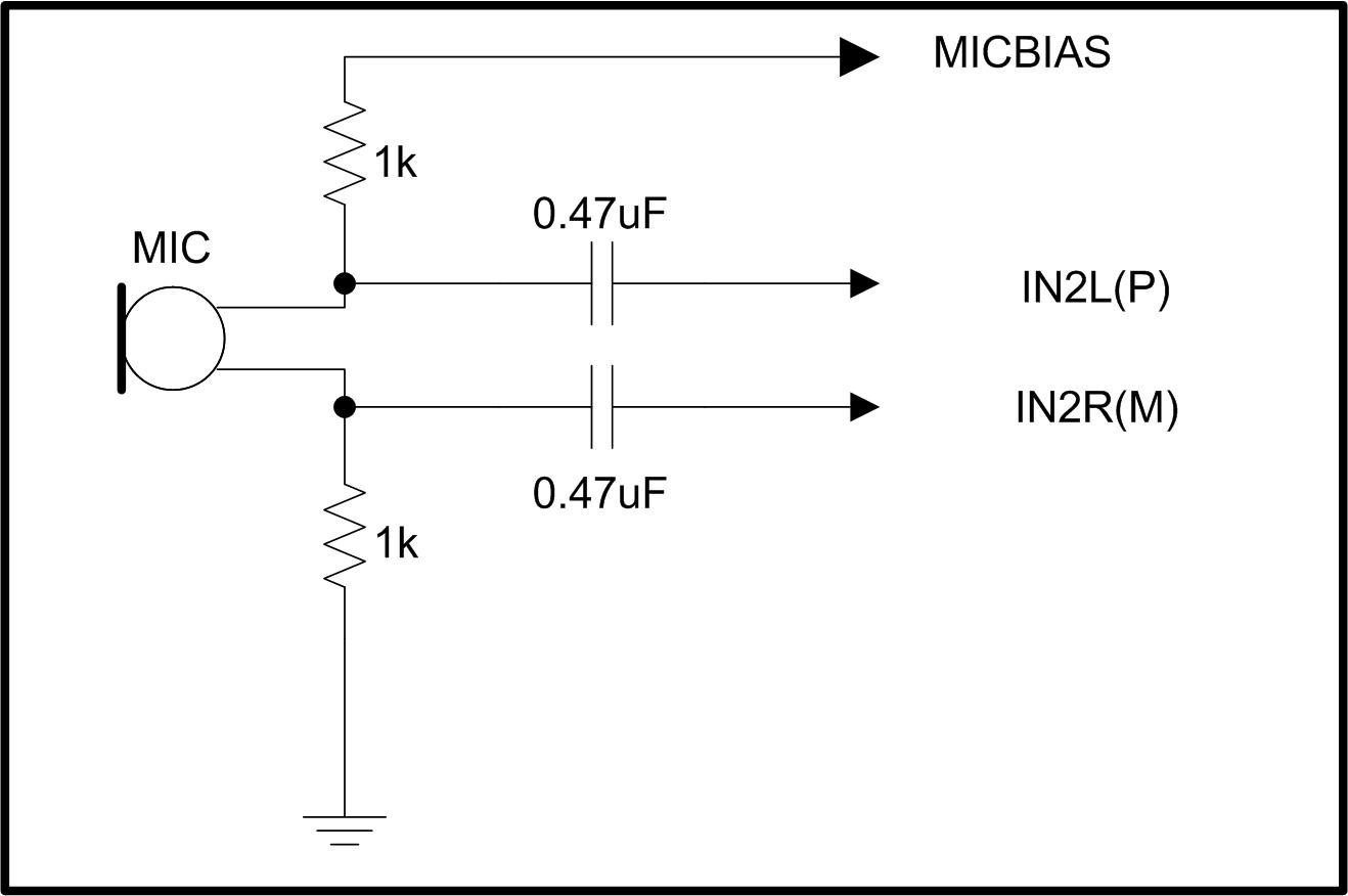
    Additionally, I recommend to take a look at this mic connections example. It is a suggested way to route the differential microphone to the IN2L/R inputs.

    Please let me know if you have further questions or comments.

    Best regards,
    Luis Fernando Rodríguez S.

  • Dear Luis Fernando,

    Thank you very much for your suggestion. We have few more clarifications.

    To explain you clearly about our MIC interface section;

    Our design is basically voice recognition system, which utilizes multiple MICs to improve the speech quality.

    1.  In our design we have MICs processing board, which process the multiple MICs data and provide single MIC out  as a Differential/Balanced.

    Balanced MIC output is connected to the CODEC (TLV320AIC320) without MIC Bias resistors (MIC bias-1K & 1K to GND)....Please comment on this architecture.

    2. And also We have another clarification about the CODEC mixing function;

    kindly provide us the more data(application and configuration) about the mixing of multiple analog inputs.

    3. Another clarification about the CM voltage 0.75V and 0.9V defined for single/differential applications. I believe CM refers to common mode voltage.

    Kindly clarify the need of different voltage levels(0.75V/0.9V) for signaling schemes.

    Best Regards,

    Hema Sundar

  • Hello, Hema,

    1. If the MICs data is already processed, there's no need to add a MICBIAS resistor from MICBIAS pin to IN2L(P) pin (MICBIAS code line can be omitted in my previous configuration). So, balanced MIC inputs can be connected directly to IN2L (P) and IN2R (M) through the 0.47uF DC-blocking capacitors. There's no need to add the 1kohm resistor.

    2. Do you need a specific mixer configuration? Which inputs would you like to mix? The analog inputs can be routed at the PGA input. All the P-input signals would be mixed and all the M-input signals would be routed as well. Please see analog routing diagram for details (www.ti.com/.../slaa557.pdf

    3. That's correct. CM voltage refers to the common-mode voltage. This is recommended to be used in single-ended applications. The common-mode voltage would depend of you input voltage. It could allow a higher full-scale voltage. See electrical characteristics for details (www.ti.com/.../tlv320aic3204.pdf

    Best regards,
    Luis Fernando Rodríguez S.