This thread has been locked.

If you have a related question, please click the "Ask a related question" button in the top right corner. The newly created question will be automatically linked to this question.

Linux/TLV320AIC3106: Issue with digital effects LB1 and LB2 of TLV320AIC3106

Part Number: TLV320AIC3106

Tool/software: Linux

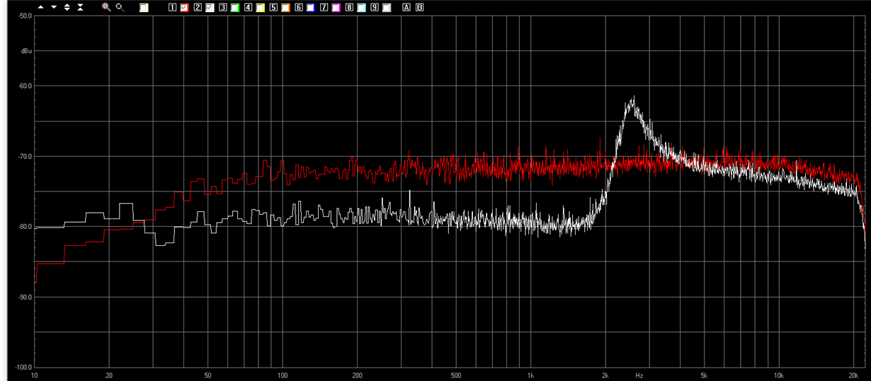
I'm trying to use the digital effects LB1 and LB2 of TLV320AIC3106. What I need is a filter with +10dB at 2500Hz. I designed it with TIbq tool, but what I obtain from the codec is that in the following picture:

The filter is acting on a white noise (in red, the original noise spectrum). After enabling the filter, the result is visible in the white signal: the filter acts by adding +10dB at 2500Hz, but at the frequencies below this, it operates an unexpected attenuation.

The result is the same even acting with a second filter in another frequency: at frequencies below the lowest, the codec operates an attenuation of approx. 10dB. (NOTE: the de-emphasis filter is disabled)

Can anyone help me eliminating this unwanted attenuation?

  • Hi,

    Welcome to E2E and thank you for your interest in our products!

    Could you provide a screenshot of the TIBQ configuration that you used to get the coefficient values? Additionally, could you provide the TLV320AIC3106 register configuration? This is to verify if all the settings are correct.

    Thank you.

    Best regards,
    Luis Fernando Rodríguez S.
  • Thanks for your answer,

    I'm working on the TI's audio codec tlv320aic3106. I need to process the signal using the  digital processing blocks LB1 (and LB2): page 28 of the attached datasheet.
    Using the Ti's biquadratic tool (http://www.ti.com/tool/coefficient-calc), I designed a +10dB filter, acting at 2500Hz, with 500Hz bandwidth.
    The output of this calculus is in the file "Coefficients_MTS4.txt", inside the compressed archive.
    The python script converts that file into a bash script for programming the registers into the device (automating the operation).
    The problem I encountered is that the filter acts at 2500Hz, but operates a deep attenuation below this frequency (approx. 10dB, visible in the file "digital_filter_2500Hz_500HzBW_10dB.png"). I need to know how to avoid this attenuation and make the filter work properly, like the behavior displayed in the TIbq tool.

    ATTENTION: the password to unzip the archive is "digital" .

    Thanks

    Dino Spiller
    Electronics Product Development

    VIMAR SpA
    Tel. +39 0424 488 113
    dino.spiller@vimar.com
    Rispetta l'ambiente. Stampa solo se necessario.
    Take care of the environment. print only if necessary.


    Da: Luis Fernando Rodríguez S. <bounce-4296757@mail.e2e.ti.com>
    Inviato: martedì 28 febbraio 2017 21.56.58
    A: AudioConvertersForum@mail.e2e.ti.com
    Oggetto: Audio Converters Forum: Linux/TLV320AIC3106: Issue with digital effects LB1 and LB2 of TLV320AIC3106


    A Message from the TI E2E™ Community
    Texas Instruments


    Luis Fernando Rodríguez S. replied to Linux/TLV320AIC3106: Issue with digital effects LB1 and LB2 of TLV320AIC3106.

    Hi,

    Welcome to E2E and thank you for your interest in our products!

    Could you provide a screenshot of the TIBQ configuration that you used to get the coefficient values? Additionally, could you provide the TLV320AIC3106 register configuration? This is to verify if all the settings are correct.

    Thank you.

    Best regards,
    Luis Fernando Rodríguez S.


    You received this notification because you subscribed to the forum.  To unsubscribe from only this thread, go here.

    Flag this post as spam/abuse.

  • Good morning,

    any news about the issue?

    Thanks

    Dino

  • Good morning, Dino,

    I apologize for the late response.

    I have been making some tests on my boards and your configuration. I will answer as soon as I get the test results.

    Thank you.

    Best regards,
    Luis Fernando Rodríguez S.
  • Hi, Dino,

    I finalized the tests with the coefficients values that you sent me. But I'm getting different results. Please take a look at the picture below:

    The test was made with a 0.5FFS signal. I used the script below to configure the codec:

    w 30 00 00
    w 30 00 80
    w 30 07 8A
    w 30 25 C0
    w 30 29 02
    w 30 2B 00
    w 30 52 80
    w 30 5C 80
    w 30 4B 80
    w 30 4E 80
    w 30 56 09
    w 30 5D 09
    w 30 4F 09
    w 30 00 00
    w 30 0c 0a
    w 30 00 01
    w 30 01 7f ff 94 30 66 12
    w 30 0d 73 d5 88 d0

    It is in hex format w (write) 30 (I2C address) xx (register address) yy (register data) zz (next register data).

    Are you using a similar configuration for the rest of the codec settings?

    Additionally, I attached a complete block diagram for a complete understanding of the TLV320AIC3106 behavior.

    6663.AIC3106_Block_Diagram(0 9).pdf

    Please let me know if you have additional questions or comments about this issue.

    Best regards,
    Luis Fernando Rodríguez S.

  • Hi Luis Fernando,

    thanks for your answer. Today/tomorrow I'm going to build a dumper in order to monitor all the registers (since the codec is driven by an ALSA driver, many settings are performed by this) and verify if there is something unexpected in the registers. Eventually I will disable the ALSA driver and perform the test "raw".

    In the meanwhile I'd like to ask you 3 questions:

    1) in the second instruction reported in your last post, you wrote 0x80 in the register 0: reading the datasheet, it seems you wrote "1" in a "reserved bit field", where the datasheet recommends to write only 0. Why did you do this? Do I have to do the same?

    If I understood well reading your register configuration, you applied the 0.5FFS signal to the input of the codec, and the DAC replicated the signal to the output, prior digital processing. The question is:

    2) can you confirm you bypassed the I2S stream connecting input to output, or did you feed the signal through I2S?

    3) in which format is your stimulation signal (0.5FFS signal)? (e.g. wav file...) Could you share this to me?

    Thanks

    Dino

  • Hi, Dino,

    1) My mistake, I added this line to make a software reset. It should be register 1.

    2) I sent this signal via I2S with an audio precision tool. Basically, this test was used to verify the biquad filter coefficients and its behavior. The coefficients that you sent me work as expected based on this test. Which means that the problem should be in the rest of the codec configuration.

    3) I sent the 0.5FFS signal with an audio precision tool. The signal was in I2S format (16-bits, 2s-complement, signed).

    Please let me know if you were able to get the register configuration. I may test it on my evaluation board and send you the new results.

    Thank you.

    Best regards,
    Luis Fernando Rodríguez S.
  • Thanks again for your answer.

    Attached is a compressed archive with the dump result (before the register settings, after register setting and after a second play with ALSA).

    I found a problem with ALSA (it modifies the coefficients), but this is a minor issue and I'm working on it.

    The most important thing is that I found an overload FLAG in the DAC (register 0B).

    I'm investigating on it. Unfortunately the TIBQ doesn't provide away to decrease the DC gain of the biquadratic filters, so I'm  working with Matlab, for doing this.

    Let me know if you note somethig "strange" in the dump files.

    NOTE: in order to see the differences in the registers I used a simple diff tool with the txt files attached.

    Regards

    Dinocodec_problems.zip

  • Hi, Dino,

    Do you have information about the sent data? The overflow flag is enabled when the digital data reaches the full-scale voltage (0x7fff at 16-bits). The gain doesn't seem to be the root cause since the DAC volume is configured at -53.5dB.

    Best regards,
    Luis Fernando Rodríguez S.
  • Hi Luis,

    I solved the problem related to the ALSA play: it was because in my script I forgot to swhitch-back the codec to register's page 0. Nevertheless, unfortunately the problem is still the same.

    The signal I used I used is the whitenoise signal attached:

    I am starting to think I cannot use those biquadratic filters as 2 bands of a graphic equalizer. Is it?

    Thanks for your help,

    Dino

  • Hi, Dino,

    In your application, are you using the following register configuration sequence?

    - Modify the filter coefficients.
    - Enable the digital filter blocks.
    - Power up the DAC blocks.

    Best regards,
    Luis Fernando Rodríguez S.
  • Hi Luis,

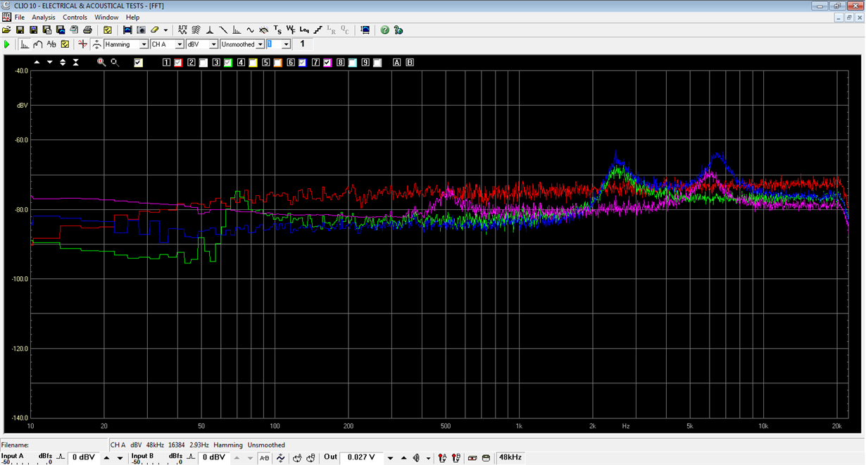
    I modified a little the script, so that the sequence now is the same as you recommended. The problem is always the same. In the picture below you can observe the behavior with different filters: the effect is always an attenuation below the lowest frequency.

    Did you try something with the whitenoise I provided you?

    What are your results?

    Thanks

  • Hi, Dino,

    I got different results with your audio file. I compared the white noise file from my AP with your attached white noise file. Please see the results below (yellow graph is the AP noise file and the blue one is your noise file).

    It seems that the BQ filter is working correctly with the white noise file from the AP.

    Best regards,
    Luis Fernando Rodríguez S.