This thread has been locked.

If you have a related question, please click the "Ask a related question" button in the top right corner. The newly created question will be automatically linked to this question.

TLV320AIC3254: TLV320AIC3254 - Noise Threshold

Part Number: TLV320AIC3254

Hello,

using the Evaluation Board for the above audio codec, I want to check out the Noise Threshold feature.
When I reduce the input signal, the Noise Threshold flag is set (Page 0, Register 47). When I increase the input signal, the Noise Threshold flag is reset. This works as expected for for noise threshold levels down to -74dB.

When I further reduce the Noise Threshold setting (-76dB, - 78dB, -80dB, ...) the Noise Threshold Flag is never set. Since I assumed that the input signal picks up any distortion, I short circuited the input signals. But the result was the same: Configuring the Noise Threshold to -76dB and lower, the Noise Threshold Flag is never set.

I use IN3L / IN3R in differential mode.

These are my questions:

  1. Why do Noise Threshold Levels lower than -74dB not work?
  2. What are the parameters that do influence the Noise Treshold? (e.g. Is there a relation betwenn the Noise Threshold and the Clock, the power supplies, ...)

Here are the settings that I use:

w 30 00 00
w 30 01 01
w 30 00 00
w 30 37 02
w 30 38 02
w 30 00 00
w 30 04 00
w 30 05 11
w 30 06 04
w 30 07 00
w 30 08 00
w 30 19 00
w 30 1A 01
w 30 12 81
w 30 13 82
w 30 14 80
w 30 0B 81
w 30 0C 82
w 30 0D 00
w 30 0E 80
w 30 00 00
w 30 1B 0C
w 30 1C 00
w 30 1D 17
w 30 1E 84
w 30 1F 00
w 30 20 00
w 30 21 10
w 30 00 01
w 30 01 08
w 30 02 A1
w 30 0A 40
w 30 47 32
w 30 7B 01
w 30 00 01
w 30 34 04
w 30 36 04
w 30 37 00
w 30 39 00
w 30 00 00
w 30 51 C0
w 30 52 00
w 30 00 01
w 30 3D 00
w 30 00 00
w 30 3F D4
w 30 40 00
w 30 00 00
w 30 56 F0
w 30 57 6A
w 30 58 46
w 30 59 05
w 30 5A 05
w 30 5B 00
w 30 5C 00
w 30 5E F0
w 30 5F 6A
w 30 60 46
w 30 61 05
w 30 62 05
w 30 63 00
w 30 64 00
w 30 00 01
w 30 0C 08
w 30 0D 10
w 30 00 01
w 30 09 30
#w 30 09 33
w 30 00 00
w 30 53 00
w 30 54 00
w 30 41 D8
w 30 42 00
w 30 00 01
w 30 16 00
w 30 3B 00
w 30 3C 00
w 30 18 00
w 30 19 00
w 30 10 00
w 30 11 00

Best regards

Markus

  • Hi, Markus,

    I tested your configuration on my evaluation board and I got a similar behavior. In my case, the noise threshold flag changed at -80dB in some cases. When the level decreased, the flag was not enabled. I continued with the tests and it seems that this behavior also depends of the AGC max gain. When the allowed max gain was increased, the AGC noise threshold flag was set. I could get the flag set even with a noise threshold of -90dB.

    Could you try increasing the AGC max gain (page 0 / register 88 for left channel AGC and page 0 / register 96 for right channel AGC)?

    Best regards,
    Luis Fernando Rodríguez S.
  • Hello Luis,

    thank your for your fast response.

    I knew that there is a correlation between the max gain setting and the Noise Threshold as this is described in the Reference Guide (SLAU497A) in chapter 2.3.2.3 / item 5: "When AGC Noise Threshold is set to –70dB, –80dB, or –90dB, the microphone input Max PGA applicable setting must be greater than or equal to 11.5dB, 21.5dB, or 31.5dB respectively. "

    As I use a max gain setting of 35dB, I expected that a Noise Threshold down to -90dB is possible.

    As you suggested I increased the Max Gain setting to identify the lowest Noise Threshold where the Noise Flag is set. Using our Eval-Board -76dB is the lowest Noise Threshold that works with short circuited IN3L / IN3R inputs as shown below.

    Max-Gain / Noise Threshold

      30db   / -74dB
      35dB   / -74dB
      40dB   / -76dB
      45dB   / -76dB
      50dB   / -76dB
      55dB   / -76dB
      58dB   / -76dB

    Notes:

    • I only adjusted the values for Left-MIC-PGA (Page 0 / Register 88, Page 0 / Register 87, Page 0 / Register 47).
    • As we output BCLK / WCLK from the Audio Codec (Page 0 / Register 27), I removed R21 and R22 from the Eval Board.

    We created a prototype PCB. Using the same settings as for the Eval-Board, on this PCB the lowest Noise Threshold is -64dB which is even worse. So I need information on the parameters that influence the Noise Threshold behavior.

    1. Is it possible that there is a correlation with the clock signal (e.g. Jitter) ?
    2. Is it possible that there is a correlation with the supply voltages?
    3. How can I identify the relevant parameters?

    Best regards,
    Markus

  • Hello Luis,
    do you have new information for me?

    Best regards,
    Markus
  • Hi, Markus,

    I apologize for this late response. I was not able to answer before.

    Regarding your questions above, the noise threshold can be related to the board design. Each board can be different in terms of noise sensibility. Also, a noisy environment can affect the noise threshold in the board. In my evaluation board, I could set the noise threshold flag even at -90dB. Have you tried disabling the analog inputs to verify if the noise threshold flag can be set?

    Additionally, ensure that all the noise levels are decreased as much as possible. Take a look at the following article for details:

    e2e.ti.com/.../3377.common-noise-issues-in-codecs

    Please let me know if you have additional questions or comments.

    Best regards,
    Luis Fernando Rodríguez S.
  • Hello Luis,

    many thanks for your effort.
    Your answer is helpful and the summary in your article is helpful.

    I tried to verify the issue using a second Eval Board. With this EVM it was possible for me to set the noise threshold flag at -90dB. Then I searched for the differences between the two boards.

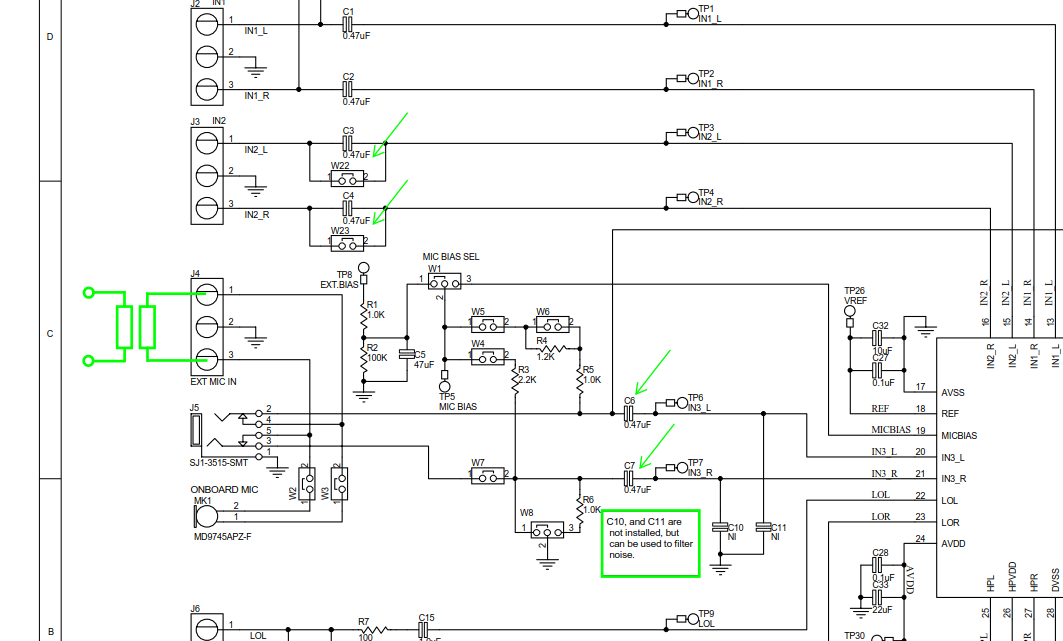
    I identified that we short circuited C6 and C7 on the affected EVM as we use a transformer for decoupling. After removing the short circuits on C6 and C7 both EVMs showed the same behaviour and I could set the noise threshold flag at -90dB.

    C6 and C7 are used to decouple the common mode voltage at IN3_L / IN3_R. In my opinion they are not required when I use an input transformer. But there was an impact on the input noise.

    1. Can you explain the background to me? (e.g. interrelation with input bias current, inequality of common mode voltage for both inputs, ...)
    2. W22 and W23 on the EVM provide the ability to short circuit the decoupling capacitors for IN2L / IN2R. This suggests that the capacitors are not necessarily required.
    3. The schematic for the EVM mentions C10 and C11 to filter noise. What are the suggested values for this capacitors? Are they helpful when using differential mode for IN3L / IN3R?

    This is an excerpt from the schematic of the EVM showing the capacitors and the input transformer:

    Best regards
    Markus

  • Hi, Markus,

    The TLV320AIC3254 has a DC-measurement mode which requires to bypass the analog inputs capacitors such C3 and C4. For this case, it is necessary to ensure that the analog inputs are in the recommended operating range (0V to AVDD). Otherwise, the analog input could be damaged. As this codec is designed for audio applications, the DC-measurement mode will not be as exact as a precision ADC, but it may be used to get an approached DC level.

    In some cases, the audio codec can be exposed to noise environments such EMI. These footprints are considered fot cases where the EVM is sensitive to this noise environment. The recommended capacitors to reduce this kind of noise is in the pF order.

    Best regards,
    Luis Fernando Rodríguez S.