This thread has been locked.

If you have a related question, please click the "Ask a related question" button in the top right corner. The newly created question will be automatically linked to this question.

TLV320AIC3204: Works half the time

Part Number: TLV320AIC3204
Other Parts Discussed in Thread: CC8520,

Hello,

I'm a bit confused with this device. I use it with a CC8520 mcu.

In DAC mode, it works all the time.

In ADC mode, it works around 1 time on 2.

When it works, it's great without cut off.

When it doesn't work, I have some snippets of sound.

I have to turn off then on the device one time or two and it's ok.

I'm wondering if it's a clock problem, desync signal or something like that, but in DAC it's always ok.

If someone can find why it has this behavior?

Thank you

  • I found something,
    I was at 48kHz sampling rate, but if I put 32kHz I have more sound than cut off when it doesn't work.
    I think it's a sync issue, MCLK is generated by mcu, maybe I have to use the PLL of the codec?
    Can someone help me with that?
  • An other thing,
    Sometime, sound is mute and then it's powering slowly. Maybe it's a problem of initialization time, I tried changing MICPGA startup delay and Reference charging time but no difference..
  • Hi, Frederic,

    Could you provide your register configuration, please? Additionally, could you provide the MCLK frequency that you are using? If you are using the device in slave mode, could you provide the BCLK and WCLK frequencies? Finally, what sampling rate will you be using?

    Thank you.

    Best regards,
    Luis Fernando Rodríguez S.
  • Hello Louis,

    Thank you for your answer.

    Here my config file :

    jack.txt
    <!DOCTYPE devcfg SYSTEM "devcfg.dtd"[]>
    <devcfg>
    <name>jack</name>
    <type>Master/Stereo input base station</type>
    <hardware_platform>Custom design</hardware_platform>
    <operation>Autonomous</operation>
    <usb_descriptor></usb_descriptor>
    <mini_prod_test_en>0</mini_prod_test_en>
    <pwc_rev>1.4.2</pwc_rev>
    <desc>Audio connections:
    - Audio input: LINE IN
    - Audio output: LINE OUT + HEADPHONE
    
    User interface:
    - Pairing button: SW9 (click)
    - Network status LED: D9</desc>
    <task>
    <name>Advanced Options</name>
    <attr>
    <name>Acquire timeslot period</name>
    <value>5750 us</value>
    </attr>
    <attr>
    <name>Fade out when muting</name>
    <value>1</value>
    </attr>
    <attr>
    <name>Protocol version</name>
    <value>0</value>
    </attr>
    <attr>
    <name>RF data rate</name>
    <value>5 Mbps</value>
    </attr>
    <attr>
    <name>Store dynamic audio channel selection</name>
    <value>0</value>
    </attr>
    <attr>
    <name>Store local input volume</name>
    <value>1</value>
    </attr>
    <attr>
    <name>Store local output balance</name>
    <value>1</value>
    </attr>
    <attr>
    <name>Store local output volume</name>
    <value>1</value>
    </attr>
    <attr>
    <name>Store network ID</name>
    <value>1</value>
    </attr>
    <attr>
    <name>Store remote input volume</name>
    <value>1</value>
    </attr>
    <attr>
    <name>Store remote output volume</name>
    <value>1</value>
    </attr>
    <attr>
    <name>Timeslot alignment</name>
    <value>Disabled</value>
    </attr>
    <attr>
    <name>Timeslot period</name>
    <value>Maximize average capacity</value>
    </attr>
    </task>
    <task>
    <name>Audio Device Customization</name>
    <attr>
    <name>ACTIVE to LOW-POWER</name>
    <value></value>
    </attr>
    <attr>
    <name>Enable digital audio input valid pin</name>
    <value>0</value>
    </attr>
    <attr>
    <name>INACTIVE to LOW-POWER</name>
    <value>w 30 00 00    # Select register page 0
    w 30 51 C0    # Power up ADC channels</value>
    </attr>
    <attr>
    <name>INACTIVE to SR-SWITCH</name>
    <value></value>
    </attr>
    <attr>
    <name>LOW-POWER to ACTIVE</name>
    <value></value>
    </attr>
    <attr>
    <name>LOW-POWER to INACTIVE</name>
    <value>w 30 00 01    # Select register page 1
    w 30 3B 80    # Set minimum left MICPGA gain
    w 30 3C 80    # Set minimum right MICPGA gain
    w 30 00 00    # Select register page 0
    w 30 52 88    # Mute ADC channels
    w 30 51 00    # Power down ADC channels</value>
    </attr>
    <attr>
    <name>OFF to SR-SWITCH</name>
    <value># PIN RESET
    p Reset 1     # Release the reset pin
    # RESET
    w 30 00 00    # Select register page 0
    w 30 01 01    # I2C reset
    # CLOCK SETTINGS
    w 30 12 81    # Power up the NADC divider with value 1
    w 30 13 82    # Power up the MADC divider with value 2
    w 30 14 80    # Program OSR for ADC to 128
    # DIGITAL INTERFACE
    w 30 1B 20    # I2S, 24-bit, BCLK and WCLK are inputs
    # PROCESSING BLOCK USAGE
    w 30 3D 01    # Select ADC processing block PRB_R1
    # ANALOG POWER SUPPLY
    w 30 00 01    # Select register page 1
    w 30 01 08    # Disable internal crude AVDD before powering up the internal AVDD LDO
    w 30 02 01    # Enable internal analog LDO, analog blocks powered
    w 30 0A 00    # Common mode set to 0.9V
    # MICPGA DELAY, REFERENCE CHARGING AND HEADPHONE DE-POP
    w 30 47 31    # MICPGA startup delay is 3 ms
    w 30 7B 01    # Reference charging time is 40 ms
    # AUDIO ROUTING
    w 30 34 80    # IN1L is routed to Left MICPGA with 20K resistance
    w 30 36 80    # CM1L is routed to Left MICPGA via CM1L with 20K resistance
    w 30 37 80    # IN1R is routed to Right MICPGA with 20K resistance
    w 30 39 80    # CM1R is routed to Right MICPGA via CM1R with 20K resistance
    # DC FILTER LEFT CHANNEL
    w 30 00 08    # Select register page 8
    w 30 18 7F    #                n0 + n1 * z^-1
    w 30 19 FF    #     H(z) = ----------------------
    w 30 1A 00    #               2^23 - d1 * z^-1
    w 30 1C 80    #
    w 30 1D 01    # The constants are defined as
    w 30 1E 00    #     n0 = 32767 * 256
    w 30 20 7F    #     n1 = -32767 * 256
    w 30 21 FC    #     d1 = 32768 * 256 * (1- 2^13)
    w 30 22 00    # This gives a filter with cutoff at approx. 1 Hz
    # DC FILTER RIGHT CHANNEL
    w 30 00 09    # Select register page 9
    w 30 20 7F    #                n0 + n1 * z^-1
    w 30 21 FF    #     H(z) = ----------------------
    w 30 22 00    #               2^23 - d1 * z^-1
    w 30 24 80    #
    w 30 25 01    # The constants are defined as
    w 30 26 00    #     n0 = 32767 * 256
    w 30 28 7F    #     n1 = -32767 * 256
    w 30 29 FC    #     d1 = 32768 * 256 * (1- 2^13)
    w 30 2A 00    # This gives a filter with cutoff at approx. 1 Hz</value>
    </attr>
    <attr>
    <name>SR-SWITCH 32000 to INACTIVE</name>
    <value></value>
    </attr>
    <attr>
    <name>SR-SWITCH 40275 to INACTIVE</name>
    <value></value>
    </attr>
    <attr>
    <name>SR-SWITCH 44100 to INACTIVE</name>
    <value></value>
    </attr>
    <attr>
    <name>SR-SWITCH 48000 to INACTIVE</name>
    <value></value>
    </attr>
    <attr>
    <name>SR-SWITCH to OFF</name>
    <value># PIN RESET
    p Reset 0     # Assert reset pin</value>
    </attr>
    </task>
    <task>
    <name>Audio Interface</name>
    <attr>
    <name>Audio device</name>
    <value>AIC3204</value>
    </attr>
    <attr>
    <name>BCLK multiplier</name>
    <value>64</value>
    </attr>
    <attr>
    <name>Clock source</name>
    <value>Internal with MCLK</value>
    </attr>
    <attr>
    <name>Custom setup</name>
    <value>Enabled</value>
    </attr>
    <attr>
    <name>Interface format</name>
    <value>I2S</value>
    </attr>
    <attr>
    <name>MCLK multiplier</name>
    <value>256</value>
    </attr>
    <attr>
    <name>Resolution</name>
    <value>24</value>
    </attr>
    </task>
    <task>
    <name>Audio Streaming Master Static</name>
    <attr>
    <name>Default sample rate</name>
    <value>48000</value>
    </attr>
    <attr>
    <name>M2S0 DSP IO channel</name>
    <value>0</value>
    </attr>
    <attr>
    <name>M2S0 I2S IO channel</name>
    <value>0</value>
    </attr>
    <attr>
    <name>M2S0 IO pin</name>
    <value>0</value>
    </attr>
    <attr>
    <name>M2S0 logical channel</name>
    <value>0</value>
    </attr>
    <attr>
    <name>M2S0 streaming format</name>
    <value>PCM16</value>
    </attr>
    <attr>
    <name>M2S1 DSP IO channel</name>
    <value>1</value>
    </attr>
    <attr>
    <name>M2S1 I2S IO channel</name>
    <value>1</value>
    </attr>
    <attr>
    <name>M2S1 IO pin</name>
    <value>0</value>
    </attr>
    <attr>
    <name>M2S1 logical channel</name>
    <value>1</value>
    </attr>
    <attr>
    <name>M2S1 streaming format</name>
    <value>PCM16</value>
    </attr>
    <attr>
    <name>M2S2 DSP IO channel</name>
    <value>2</value>
    </attr>
    <attr>
    <name>M2S2 I2S IO channel</name>
    <value>0</value>
    </attr>
    <attr>
    <name>M2S2 IO pin</name>
    <value>0</value>
    </attr>
    <attr>
    <name>M2S2 logical channel</name>
    <value>2</value>
    </attr>
    <attr>
    <name>M2S2 streaming format</name>
    <value>PCM16</value>
    </attr>
    <attr>
    <name>M2S3 DSP IO channel</name>
    <value>3</value>
    </attr>
    <attr>
    <name>M2S3 I2S IO channel</name>
    <value>1</value>
    </attr>
    <attr>
    <name>M2S3 IO pin</name>
    <value>0</value>
    </attr>
    <attr>
    <name>M2S3 logical channel</name>
    <value>3</value>
    </attr>
    <attr>
    <name>M2S3 streaming format</name>
    <value>PCM16</value>
    </attr>
    <attr>
    <name>M2S4 DSP IO channel</name>
    <value>4</value>
    </attr>
    <attr>
    <name>M2S4 I2S IO channel</name>
    <value>0</value>
    </attr>
    <attr>
    <name>M2S4 IO pin</name>
    <value>0</value>
    </attr>
    <attr>
    <name>M2S4 logical channel</name>
    <value>4</value>
    </attr>
    <attr>
    <name>M2S4 streaming format</name>
    <value>PCM16</value>
    </attr>
    <attr>
    <name>M2S5 DSP IO channel</name>
    <value>5</value>
    </attr>
    <attr>
    <name>M2S5 I2S IO channel</name>
    <value>1</value>
    </attr>
    <attr>
    <name>M2S5 IO pin</name>
    <value>0</value>
    </attr>
    <attr>
    <name>M2S5 logical channel</name>
    <value>5</value>
    </attr>
    <attr>
    <name>M2S5 streaming format</name>
    <value>PCM16</value>
    </attr>
    <attr>
    <name>S2M0 DSP IO channel</name>
    <value>0</value>
    </attr>
    <attr>
    <name>S2M0 I2S IO channel</name>
    <value>0</value>
    </attr>
    <attr>
    <name>S2M0 IO pin</name>
    <value>1</value>
    </attr>
    <attr>
    <name>S2M0 logical channel</name>
    <value>2</value>
    </attr>
    <attr>
    <name>S2M0 streaming format</name>
    <value>SLAC</value>
    </attr>
    <attr>
    <name>S2M1 DSP IO channel</name>
    <value>1</value>
    </attr>
    <attr>
    <name>S2M1 I2S IO channel</name>
    <value>1</value>
    </attr>
    <attr>
    <name>S2M1 IO pin</name>
    <value>0</value>
    </attr>
    <attr>
    <name>S2M1 logical channel</name>
    <value>1</value>
    </attr>
    <attr>
    <name>S2M1 streaming format</name>
    <value>PCM16</value>
    </attr>
    <attr>
    <name>S2M2 DSP IO channel</name>
    <value>2</value>
    </attr>
    <attr>
    <name>S2M2 I2S IO channel</name>
    <value>0</value>
    </attr>
    <attr>
    <name>S2M2 IO pin</name>
    <value>0</value>
    </attr>
    <attr>
    <name>S2M2 logical channel</name>
    <value>2</value>
    </attr>
    <attr>
    <name>S2M2 streaming format</name>
    <value>PCM16</value>
    </attr>
    <attr>
    <name>S2M3 DSP IO channel</name>
    <value>3</value>
    </attr>
    <attr>
    <name>S2M3 I2S IO channel</name>
    <value>1</value>
    </attr>
    <attr>
    <name>S2M3 IO pin</name>
    <value>0</value>
    </attr>
    <attr>
    <name>S2M3 logical channel</name>
    <value>3</value>
    </attr>
    <attr>
    <name>S2M3 streaming format</name>
    <value>PCM16</value>
    </attr>
    <attr>
    <name>S2M4 DSP IO channel</name>
    <value>4</value>
    </attr>
    <attr>
    <name>S2M4 I2S IO channel</name>
    <value>0</value>
    </attr>
    <attr>
    <name>S2M4 IO pin</name>
    <value>0</value>
    </attr>
    <attr>
    <name>S2M4 logical channel</name>
    <value>4</value>
    </attr>
    <attr>
    <name>S2M4 streaming format</name>
    <value>PCM16</value>
    </attr>
    <attr>
    <name>S2M5 DSP IO channel</name>
    <value>5</value>
    </attr>
    <attr>
    <name>S2M5 I2S IO channel</name>
    <value>1</value>
    </attr>
    <attr>
    <name>S2M5 IO pin</name>
    <value>0</value>
    </attr>
    <attr>
    <name>S2M5 logical channel</name>
    <value>5</value>
    </attr>
    <attr>
    <name>S2M5 streaming format</name>
    <value>PCM16</value>
    </attr>
    <attr>
    <name>SR32000 enabled</name>
    <value>0</value>
    </attr>
    <attr>
    <name>SR32000 latency</name>
    <value>2048</value>
    </attr>
    <attr>
    <name>SR40275 enabled</name>
    <value>1</value>
    </attr>
    <attr>
    <name>SR40275 latency</name>
    <value>2048</value>
    </attr>
    <attr>
    <name>SR44100 enabled</name>
    <value>1</value>
    </attr>
    <attr>
    <name>SR44100 latency</name>
    <value>2048</value>
    </attr>
    <attr>
    <name>SR48000 enabled</name>
    <value>1</value>
    </attr>
    <attr>
    <name>SR48000 latency</name>
    <value>2048</value>
    </attr>
    </task>
    <task>
    <name>Audio Streaming Slave Dynamic</name>
    <attr>
    <name>Dynamic selection count</name>
    <value>2</value>
    </attr>
    <attr>
    <name>Dynamic selection mechanism</name>
    <value>None</value>
    </attr>
    <attr>
    <name>IO pin</name>
    <value>0</value>
    </attr>
    <attr>
    <name>M2S0 logical channel</name>
    <value>0</value>
    </attr>
    <attr>
    <name>M2S1 logical channel</name>
    <value>1</value>
    </attr>
    <attr>
    <name>M2S2 logical channel</name>
    <value>2</value>
    </attr>
    <attr>
    <name>M2S3 logical channel</name>
    <value>3</value>
    </attr>
    <attr>
    <name>M2S4 logical channel</name>
    <value>4</value>
    </attr>
    <attr>
    <name>M2S5 logical channel</name>
    <value>5</value>
    </attr>
    <attr>
    <name>M2S6 logical channel</name>
    <value>6</value>
    </attr>
    <attr>
    <name>M2S7 logical channel</name>
    <value>7</value>
    </attr>
    <attr>
    <name>S2M0 logical channel</name>
    <value>2</value>
    </attr>
    <attr>
    <name>S2M1 logical channel</name>
    <value>3</value>
    </attr>
    <attr>
    <name>S2M2 logical channel</name>
    <value>4</value>
    </attr>
    <attr>
    <name>S2M3 logical channel</name>
    <value>5</value>
    </attr>
    </task>
    <task>
    <name>Audio Streaming Slave EHIF</name>
    <attr>
    <name>M2S0 DSP IO channel</name>
    <value>0</value>
    </attr>
    <attr>
    <name>M2S0 I2S IO channel</name>
    <value>0</value>
    </attr>
    <attr>
    <name>M2S0 IO pin</name>
    <value>0</value>
    </attr>
    <attr>
    <name>M2S1 DSP IO channel</name>
    <value>1</value>
    </attr>
    <attr>
    <name>M2S1 I2S IO channel</name>
    <value>1</value>
    </attr>
    <attr>
    <name>M2S1 IO pin</name>
    <value>0</value>
    </attr>
    <attr>
    <name>M2S2 DSP IO channel</name>
    <value>2</value>
    </attr>
    <attr>
    <name>M2S2 I2S IO channel</name>
    <value>0</value>
    </attr>
    <attr>
    <name>M2S2 IO pin</name>
    <value>0</value>
    </attr>
    <attr>
    <name>M2S3 DSP IO channel</name>
    <value>3</value>
    </attr>
    <attr>
    <name>M2S3 I2S IO channel</name>
    <value>1</value>
    </attr>
    <attr>
    <name>M2S3 IO pin</name>
    <value>0</value>
    </attr>
    <attr>
    <name>M2S4 DSP IO channel</name>
    <value>4</value>
    </attr>
    <attr>
    <name>M2S4 I2S IO channel</name>
    <value>0</value>
    </attr>
    <attr>
    <name>M2S4 IO pin</name>
    <value>0</value>
    </attr>
    <attr>
    <name>M2S5 DSP IO channel</name>
    <value>5</value>
    </attr>
    <attr>
    <name>M2S5 I2S IO channel</name>
    <value>1</value>
    </attr>
    <attr>
    <name>M2S5 IO pin</name>
    <value>0</value>
    </attr>
    <attr>
    <name>S2M0 DSP IO channel</name>
    <value>0</value>
    </attr>
    <attr>
    <name>S2M0 I2S IO channel</name>
    <value>0</value>
    </attr>
    <attr>
    <name>S2M0 IO pin</name>
    <value>0</value>
    </attr>
    <attr>
    <name>S2M1 DSP IO channel</name>
    <value>1</value>
    </attr>
    <attr>
    <name>S2M1 I2S IO channel</name>
    <value>1</value>
    </attr>
    <attr>
    <name>S2M1 IO pin</name>
    <value>0</value>
    </attr>
    <attr>
    <name>S2M2 DSP IO channel</name>
    <value>2</value>
    </attr>
    <attr>
    <name>S2M2 I2S IO channel</name>
    <value>0</value>
    </attr>
    <attr>
    <name>S2M2 IO pin</name>
    <value>0</value>
    </attr>
    <attr>
    <name>S2M3 DSP IO channel</name>
    <value>3</value>
    </attr>
    <attr>
    <name>S2M3 I2S IO channel</name>
    <value>1</value>
    </attr>
    <attr>
    <name>S2M3 IO pin</name>
    <value>0</value>
    </attr>
    <attr>
    <name>S2M4 DSP IO channel</name>
    <value>4</value>
    </attr>
    <attr>
    <name>S2M4 I2S IO channel</name>
    <value>0</value>
    </attr>
    <attr>
    <name>S2M4 IO pin</name>
    <value>0</value>
    </attr>
    <attr>
    <name>S2M5 DSP IO channel</name>
    <value>5</value>
    </attr>
    <attr>
    <name>S2M5 I2S IO channel</name>
    <value>1</value>
    </attr>
    <attr>
    <name>S2M5 IO pin</name>
    <value>0</value>
    </attr>
    </task>
    <task>
    <name>Audio Streaming Slave Static</name>
    <attr>
    <name>M2S0 DSP IO channel</name>
    <value>0</value>
    </attr>
    <attr>
    <name>M2S0 I2S IO channel</name>
    <value>0</value>
    </attr>
    <attr>
    <name>M2S0 IO pin</name>
    <value>0</value>
    </attr>
    <attr>
    <name>M2S0 logical channel</name>
    <value>0</value>
    </attr>
    <attr>
    <name>M2S1 DSP IO channel</name>
    <value>1</value>
    </attr>
    <attr>
    <name>M2S1 I2S IO channel</name>
    <value>1</value>
    </attr>
    <attr>
    <name>M2S1 IO pin</name>
    <value>0</value>
    </attr>
    <attr>
    <name>M2S1 logical channel</name>
    <value>1</value>
    </attr>
    <attr>
    <name>M2S2 DSP IO channel</name>
    <value>2</value>
    </attr>
    <attr>
    <name>M2S2 I2S IO channel</name>
    <value>0</value>
    </attr>
    <attr>
    <name>M2S2 IO pin</name>
    <value>0</value>
    </attr>
    <attr>
    <name>M2S2 logical channel</name>
    <value>2</value>
    </attr>
    <attr>
    <name>M2S3 DSP IO channel</name>
    <value>3</value>
    </attr>
    <attr>
    <name>M2S3 I2S IO channel</name>
    <value>1</value>
    </attr>
    <attr>
    <name>M2S3 IO pin</name>
    <value>0</value>
    </attr>
    <attr>
    <name>M2S3 logical channel</name>
    <value>3</value>
    </attr>
    <attr>
    <name>M2S4 DSP IO channel</name>
    <value>4</value>
    </attr>
    <attr>
    <name>M2S4 I2S IO channel</name>
    <value>0</value>
    </attr>
    <attr>
    <name>M2S4 IO pin</name>
    <value>0</value>
    </attr>
    <attr>
    <name>M2S4 logical channel</name>
    <value>4</value>
    </attr>
    <attr>
    <name>M2S5 DSP IO channel</name>
    <value>5</value>
    </attr>
    <attr>
    <name>M2S5 I2S IO channel</name>
    <value>1</value>
    </attr>
    <attr>
    <name>M2S5 IO pin</name>
    <value>0</value>
    </attr>
    <attr>
    <name>M2S5 logical channel</name>
    <value>5</value>
    </attr>
    <attr>
    <name>S2M0 DSP IO channel</name>
    <value>0</value>
    </attr>
    <attr>
    <name>S2M0 I2S IO channel</name>
    <value>0</value>
    </attr>
    <attr>
    <name>S2M0 IO pin</name>
    <value>0</value>
    </attr>
    <attr>
    <name>S2M0 logical channel</name>
    <value>0</value>
    </attr>
    <attr>
    <name>S2M1 DSP IO channel</name>
    <value>1</value>
    </attr>
    <attr>
    <name>S2M1 I2S IO channel</name>
    <value>1</value>
    </attr>
    <attr>
    <name>S2M1 IO pin</name>
    <value>0</value>
    </attr>
    <attr>
    <name>S2M1 logical channel</name>
    <value>1</value>
    </attr>
    <attr>
    <name>S2M2 DSP IO channel</name>
    <value>2</value>
    </attr>
    <attr>
    <name>S2M2 I2S IO channel</name>
    <value>0</value>
    </attr>
    <attr>
    <name>S2M2 IO pin</name>
    <value>0</value>
    </attr>
    <attr>
    <name>S2M2 logical channel</name>
    <value>2</value>
    </attr>
    <attr>
    <name>S2M3 DSP IO channel</name>
    <value>3</value>
    </attr>
    <attr>
    <name>S2M3 I2S IO channel</name>
    <value>1</value>
    </attr>
    <attr>
    <name>S2M3 IO pin</name>
    <value>0</value>
    </attr>
    <attr>
    <name>S2M3 logical channel</name>
    <value>3</value>
    </attr>
    <attr>
    <name>S2M4 DSP IO channel</name>
    <value>4</value>
    </attr>
    <attr>
    <name>S2M4 I2S IO channel</name>
    <value>0</value>
    </attr>
    <attr>
    <name>S2M4 IO pin</name>
    <value>0</value>
    </attr>
    <attr>
    <name>S2M4 logical channel</name>
    <value>4</value>
    </attr>
    <attr>
    <name>S2M5 DSP IO channel</name>
    <value>5</value>
    </attr>
    <attr>
    <name>S2M5 I2S IO channel</name>
    <value>1</value>
    </attr>
    <attr>
    <name>S2M5 IO pin</name>
    <value>0</value>
    </attr>
    <attr>
    <name>S2M5 logical channel</name>
    <value>5</value>
    </attr>
    </task>
    <task>
    <name>Audio Streaming USB Static</name>
    <attr>
    <name>M2S0 logical channel</name>
    <value>0</value>
    </attr>
    <attr>
    <name>M2S0 streaming format</name>
    <value>PCM16</value>
    </attr>
    <attr>
    <name>M2S1 logical channel</name>
    <value>1</value>
    </attr>
    <attr>
    <name>M2S1 streaming format</name>
    <value>PCM16</value>
    </attr>
    <attr>
    <name>M2S2 logical channel</name>
    <value>2</value>
    </attr>
    <attr>
    <name>M2S2 streaming format</name>
    <value>PCM16</value>
    </attr>
    <attr>
    <name>M2S3 logical channel</name>
    <value>3</value>
    </attr>
    <attr>
    <name>M2S3 streaming format</name>
    <value>PCM16</value>
    </attr>
    <attr>
    <name>M2S4 logical channel</name>
    <value>4</value>
    </attr>
    <attr>
    <name>M2S4 streaming format</name>
    <value>PCM16</value>
    </attr>
    <attr>
    <name>M2S5 logical channel</name>
    <value>5</value>
    </attr>
    <attr>
    <name>M2S5 streaming format</name>
    <value>PCM16</value>
    </attr>
    <attr>
    <name>S2M0 logical channel</name>
    <value>0</value>
    </attr>
    <attr>
    <name>S2M0 streaming format</name>
    <value>PCM16</value>
    </attr>
    <attr>
    <name>S2M1 logical channel</name>
    <value>1</value>
    </attr>
    <attr>
    <name>S2M1 streaming format</name>
    <value>PCM16</value>
    </attr>
    <attr>
    <name>S2M2 logical channel</name>
    <value>2</value>
    </attr>
    <attr>
    <name>S2M2 streaming format</name>
    <value>PCM16</value>
    </attr>
    <attr>
    <name>S2M3 logical channel</name>
    <value>3</value>
    </attr>
    <attr>
    <name>S2M3 streaming format</name>
    <value>PCM16</value>
    </attr>
    <attr>
    <name>S2M4 logical channel</name>
    <value>4</value>
    </attr>
    <attr>
    <name>S2M4 streaming format</name>
    <value>PCM16</value>
    </attr>
    <attr>
    <name>S2M5 logical channel</name>
    <value>5</value>
    </attr>
    <attr>
    <name>S2M5 streaming format</name>
    <value>PCM16</value>
    </attr>
    <attr>
    <name>SR32000 enabled</name>
    <value>0</value>
    </attr>
    <attr>
    <name>SR32000 latency</name>
    <value>1024</value>
    </attr>
    <attr>
    <name>SR44100 enabled</name>
    <value>0</value>
    </attr>
    <attr>
    <name>SR44100 latency</name>
    <value>1024</value>
    </attr>
    <attr>
    <name>SR48000 enabled</name>
    <value>1</value>
    </attr>
    <attr>
    <name>SR48000 latency</name>
    <value>1024</value>
    </attr>
    </task>
    <task>
    <name>Device Identification</name>
    <attr>
    <name>Manufacturer ID</name>
    <value>00000001</value>
    </attr>
    <attr>
    <name>Product ID</name>
    <value>00000003</value>
    </attr>
    <attr>
    <name>Product name</name>
    <value>jack</value>
    </attr>
    <attr>
    <name>USB device release</name>
    <value></value>
    </attr>
    <attr>
    <name>USB product ID</name>
    <value></value>
    </attr>
    <attr>
    <name>USB vendor ID</name>
    <value></value>
    </attr>
    </task>
    <task>
    <name>Human Interface Device</name>
    <attr>
    <name>HID feature set</name>
    <value>Play control</value>
    </attr>
    </task>
    <task>
    <name>IO Mapping</name>
    <attr>
    <name>Active IO level</name>
    <value>00000</value>
    </attr>
    <attr>
    <name>Alternate network status LED</name>
    <value></value>
    </attr>
    <attr>
    <name>Audio channel selection bit 0</name>
    <value></value>
    </attr>
    <attr>
    <name>Audio channel selection bit 1</name>
    <value></value>
    </attr>
    <attr>
    <name>Audio channel selection bit 2</name>
    <value></value>
    </attr>
    <attr>
    <name>Audio channel selection button</name>
    <value></value>
    </attr>
    <attr>
    <name>Audio device PVDD control</name>
    <value></value>
    </attr>
    <attr>
    <name>Audio device reset control</name>
    <value>GIO1</value>
    </attr>
    <attr>
    <name>Digital audio input valid</name>
    <value>GIO12</value>
    </attr>
    <attr>
    <name>External host interface interrupt</name>
    <value>GIO1</value>
    </attr>
    <attr>
    <name>Fast forward RC button</name>
    <value></value>
    </attr>
    <attr>
    <name>Fast forward RC output</name>
    <value></value>
    </attr>
    <attr>
    <name>Input volume mute RC button</name>
    <value></value>
    </attr>
    <attr>
    <name>Input volume mute RC output</name>
    <value></value>
    </attr>
    <attr>
    <name>Local input volume down button</name>
    <value></value>
    </attr>
    <attr>
    <name>Local input volume mute button</name>
    <value></value>
    </attr>
    <attr>
    <name>Local input volume up button</name>
    <value></value>
    </attr>
    <attr>
    <name>Local output volume down button</name>
    <value></value>
    </attr>
    <attr>
    <name>Local output volume mute button</name>
    <value></value>
    </attr>
    <attr>
    <name>Local output volume up button</name>
    <value></value>
    </attr>
    <attr>
    <name>Mini production test control</name>
    <value></value>
    </attr>
    <attr>
    <name>Network pairing button</name>
    <value>CSN(H)</value>
    </attr>
    <attr>
    <name>Network standby control button</name>
    <value></value>
    </attr>
    <attr>
    <name>Network standby disable RC button</name>
    <value></value>
    </attr>
    <attr>
    <name>Network standby disable RC output</name>
    <value></value>
    </attr>
    <attr>
    <name>Network standby enable RC button</name>
    <value></value>
    </attr>
    <attr>
    <name>Network standby enable RC output</name>
    <value></value>
    </attr>
    <attr>
    <name>Network standby toggle RC button</name>
    <value></value>
    </attr>
    <attr>
    <name>Network standby toggle RC output</name>
    <value></value>
    </attr>
    <attr>
    <name>Network status LED</name>
    <value>GIO9_AD2</value>
    </attr>
    <attr>
    <name>Output balance left button</name>
    <value></value>
    </attr>
    <attr>
    <name>Output balance right button</name>
    <value></value>
    </attr>
    <attr>
    <name>Output volume decrement RC button</name>
    <value></value>
    </attr>
    <attr>
    <name>Output volume decrement RC output</name>
    <value></value>
    </attr>
    <attr>
    <name>Output volume increment RC button</name>
    <value></value>
    </attr>
    <attr>
    <name>Output volume increment RC output</name>
    <value></value>
    </attr>
    <attr>
    <name>Output volume mute RC button</name>
    <value></value>
    </attr>
    <attr>
    <name>Output volume mute RC output</name>
    <value></value>
    </attr>
    <attr>
    <name>Peripheral IO force pull in power-down</name>
    <value>00000</value>
    </attr>
    <attr>
    <name>Play-Pause RC button</name>
    <value></value>
    </attr>
    <attr>
    <name>Play-Pause RC output</name>
    <value></value>
    </attr>
    <attr>
    <name>Power control button</name>
    <value>CSN(C)</value>
    </attr>
    <attr>
    <name>Power-down indication</name>
    <value></value>
    </attr>
    <attr>
    <name>Remote input volume down button</name>
    <value></value>
    </attr>
    <attr>
    <name>Remote input volume mute button</name>
    <value></value>
    </attr>
    <attr>
    <name>Remote input volume up button</name>
    <value></value>
    </attr>
    <attr>
    <name>Remote output volume down button</name>
    <value></value>
    </attr>
    <attr>
    <name>Remote output volume mute button</name>
    <value></value>
    </attr>
    <attr>
    <name>Remote output volume up button</name>
    <value></value>
    </attr>
    <attr>
    <name>Rewind RC button</name>
    <value></value>
    </attr>
    <attr>
    <name>Rewind RC output</name>
    <value></value>
    </attr>
    <attr>
    <name>Scan next track RC button</name>
    <value></value>
    </attr>
    <attr>
    <name>Scan next track RC output</name>
    <value></value>
    </attr>
    <attr>
    <name>Scan previous track RC button</name>
    <value></value>
    </attr>
    <attr>
    <name>Scan previous track RC output</name>
    <value></value>
    </attr>
    <attr>
    <name>Timeslot alignment control input</name>
    <value></value>
    </attr>
    <attr>
    <name>Timeslot alignment control output</name>
    <value></value>
    </attr>
    </task>
    <task>
    <name>Power Management</name>
    <attr>
    <name>Input silence detection average threshold</name>
    <value>0</value>
    </attr>
    <attr>
    <name>Input silence detection peak threshold</name>
    <value>0</value>
    </attr>
    <attr>
    <name>Maximum current consumption</name>
    <value>100</value>
    </attr>
    <attr>
    <name>Power control</name>
    <value>Power toggle button</value>
    </attr>
    <attr>
    <name>Power-down on audio input silence</name>
    <value>0</value>
    </attr>
    <attr>
    <name>Power-down on audio input silence timeout</name>
    <value>1800</value>
    </attr>
    <attr>
    <name>Power-down on audio output silence</name>
    <value>0</value>
    </attr>
    <attr>
    <name>Power-down on audio output silence timeout</name>
    <value>1800</value>
    </attr>
    <attr>
    <name>Power-down on network inactivity</name>
    <value>0</value>
    </attr>
    <attr>
    <name>Power-down on network inactivity timeout</name>
    <value>300</value>
    </attr>
    <attr>
    <name>Power-reduction on audio input silence</name>
    <value>0</value>
    </attr>
    <attr>
    <name>Power-reduction on audio input silence timeout</name>
    <value>5</value>
    </attr>
    <attr>
    <name>Power-reduction on audio output silence</name>
    <value>0</value>
    </attr>
    <attr>
    <name>Power-reduction on audio output silence timeout</name>
    <value>300</value>
    </attr>
    <attr>
    <name>Power-reduction on network inactivity</name>
    <value>0</value>
    </attr>
    <attr>
    <name>Power-reduction on network inactivity timeout</name>
    <value>30</value>
    </attr>
    <attr>
    <name>Power-reduction on network standby ADD state</name>
    <value>OFF</value>
    </attr>
    <attr>
    <name>VBAT monitoring</name>
    <value>0</value>
    </attr>
    <attr>
    <name>VBAT operation threshold</name>
    <value>3.100</value>
    </attr>
    <attr>
    <name>VBAT power-up threshold</name>
    <value>3.200</value>
    </attr>
    <attr>
    <name>VBAT resistor</name>
    <value>100000</value>
    </attr>
    <attr>
    <name>VBAT warning disable threshold</name>
    <value>3.500</value>
    </attr>
    <attr>
    <name>VBAT warning enable threshold</name>
    <value>3.350</value>
    </attr>
    </task>
    <task>
    <name>Radio</name>
    <attr>
    <name>Antenna diversity enable</name>
    <value>0</value>
    </attr>
    <attr>
    <name>Default network ID</name>
    <value>FFFFFFFE</value>
    </attr>
    <attr>
    <name>Maximum slave count</name>
    <value>4</value>
    </attr>
    <attr>
    <name>Normal LBT threshold</name>
    <value>-65</value>
    </attr>
    <attr>
    <name>Pairing button enable</name>
    <value>1</value>
    </attr>
    <attr>
    <name>Pairing button timeout</name>
    <value>10</value>
    </attr>
    <attr>
    <name>Pairing filter level</name>
    <value>0</value>
    </attr>
    <attr>
    <name>Pairing mechanism</name>
    <value>Protocol master pairing signal</value>
    </attr>
    <attr>
    <name>Pairing minimum RSSI</name>
    <value>-20</value>
    </attr>
    <attr>
    <name>Product ID filter mask</name>
    <value>00000000</value>
    </attr>
    <attr>
    <name>Product ID filter ref</name>
    <value>00000000</value>
    </attr>
    <attr>
    <name>RF channel mask</name>
    <value>7fffe</value>
    </attr>
    <attr>
    <name>Range extender</name>
    <value>None</value>
    </attr>
    <attr>
    <name>Target TX power</name>
    <value>5</value>
    </attr>
    <attr>
    <name>Timeslot alignment LBT threshold</name>
    <value>-40</value>
    </attr>
    </task>
    <task>
    <name>Status Indication</name>
    <attr>
    <name>ACTIVE LED pattern</name>
    <value>0,100</value>
    </attr>
    <attr>
    <name>ALONE LED pattern</name>
    <value>0,100</value>
    </attr>
    <attr>
    <name>Alternate status LED usage</name>
    <value>None</value>
    </attr>
    <attr>
    <name>LOW BATTERY LED pattern</name>
    <value>2,23</value>
    </attr>
    <attr>
    <name>LOW BATTERY pattern enable</name>
    <value>0</value>
    </attr>
    <attr>
    <name>PAIRING LED pattern</name>
    <value>2,16,2,80</value>
    </attr>
    <attr>
    <name>Power-down indication enable</name>
    <value>0</value>
    </attr>
    <attr>
    <name>STANDBY LED pattern</name>
    <value>50,50</value>
    </attr>
    <attr>
    <name>Status LED enable</name>
    <value>1</value>
    </attr>
    </task>
    <task>
    <name>User Interface</name>
    <attr>
    <name>Button custom timing setup</name>
    <value>0</value>
    </attr>
    <attr>
    <name>Click + repeat delay</name>
    <value>40</value>
    </attr>
    <attr>
    <name>Click + repeat minimum idle time</name>
    <value>10</value>
    </attr>
    <attr>
    <name>Click + repeat period</name>
    <value>10</value>
    </attr>
    <attr>
    <name>Click maximum hold time</name>
    <value>100</value>
    </attr>
    <attr>
    <name>Click minimum idle time</name>
    <value>20</value>
    </attr>
    <attr>
    <name>Fast forward</name>
    <value>0</value>
    </attr>
    <attr>
    <name>Hold delay</name>
    <value>160</value>
    </attr>
    <attr>
    <name>Hold minimum idle time</name>
    <value>20</value>
    </attr>
    <attr>
    <name>Input volume mute</name>
    <value>0</value>
    </attr>
    <attr>
    <name>Network standby disable</name>
    <value>0</value>
    </attr>
    <attr>
    <name>Network standby enable</name>
    <value>0</value>
    </attr>
    <attr>
    <name>Network standby toggle</name>
    <value>0</value>
    </attr>
    <attr>
    <name>Output volume decrement</name>
    <value>0</value>
    </attr>
    <attr>
    <name>Output volume increment</name>
    <value>0</value>
    </attr>
    <attr>
    <name>Output volume mute</name>
    <value>0</value>
    </attr>
    <attr>
    <name>Play-Pause</name>
    <value>0</value>
    </attr>
    <attr>
    <name>Repeat delay</name>
    <value>160</value>
    </attr>
    <attr>
    <name>Repeat minimum idle time</name>
    <value>10</value>
    </attr>
    <attr>
    <name>Repeat period</name>
    <value>10</value>
    </attr>
    <attr>
    <name>Rewind</name>
    <value>0</value>
    </attr>
    <attr>
    <name>Scan next track</name>
    <value>0</value>
    </attr>
    <attr>
    <name>Scan previous track</name>
    <value>0</value>
    </attr>
    <attr>
    <name>State minimum idle time</name>
    <value>10</value>
    </attr>
    </task>
    <task>
    <name>Volume Control Master</name>
    <attr>
    <name>Local input button step amount</name>
    <value>1</value>
    </attr>
    <attr>
    <name>Local input buttons</name>
    <value>None</value>
    </attr>
    <attr>
    <name>Local input default</name>
    <value>0.0</value>
    </attr>
    <attr>
    <name>Local input fixed offset</name>
    <value>6</value>
    </attr>
    <attr>
    <name>Local input minimum</name>
    <value>0.0</value>
    </attr>
    <attr>
    <name>Local input step duration</name>
    <value>10</value>
    </attr>
    <attr>
    <name>Local output button step amount</name>
    <value>1</value>
    </attr>
    <attr>
    <name>Local output buttons</name>
    <value>None</value>
    </attr>
    <attr>
    <name>Local output default</name>
    <value>0.0</value>
    </attr>
    <attr>
    <name>Local output fixed offset</name>
    <value>0.0</value>
    </attr>
    <attr>
    <name>Local output minimum</name>
    <value>-50.0</value>
    </attr>
    <attr>
    <name>Local output step duration</name>
    <value>8</value>
    </attr>
    <attr>
    <name>Remote input button step amount</name>
    <value>1</value>
    </attr>
    <attr>
    <name>Remote input buttons</name>
    <value>None</value>
    </attr>
    <attr>
    <name>Remote input default</name>
    <value>0.0</value>
    </attr>
    <attr>
    <name>Remote input minimum</name>
    <value>0.0</value>
    </attr>
    <attr>
    <name>Remote output button step amount</name>
    <value>1</value>
    </attr>
    <attr>
    <name>Remote output buttons</name>
    <value>None</value>
    </attr>
    <attr>
    <name>Remote output default</name>
    <value>0.0</value>
    </attr>
    <attr>
    <name>Remote output minimum</name>
    <value>-50.0</value>
    </attr>
    </task>
    <task>
    <name>Volume Control Slave</name>
    <attr>
    <name>Local input button step amount</name>
    <value>1</value>
    </attr>
    <attr>
    <name>Local input buttons</name>
    <value>None</value>
    </attr>
    <attr>
    <name>Local input control source</name>
    <value>Local</value>
    </attr>
    <attr>
    <name>Local input default</name>
    <value>0.0</value>
    </attr>
    <attr>
    <name>Local input fixed offset</name>
    <value>0.0</value>
    </attr>
    <attr>
    <name>Local input minimum</name>
    <value>0.0</value>
    </attr>
    <attr>
    <name>Local input multi-channel offset enable</name>
    <value>0</value>
    </attr>
    <attr>
    <name>Local input step duration</name>
    <value>8</value>
    </attr>
    <attr>
    <name>Local output button step amount</name>
    <value>1</value>
    </attr>
    <attr>
    <name>Local output buttons</name>
    <value>None</value>
    </attr>
    <attr>
    <name>Local output control source</name>
    <value>Local</value>
    </attr>
    <attr>
    <name>Local output default</name>
    <value>0.0</value>
    </attr>
    <attr>
    <name>Local output fixed offset</name>
    <value>0.0</value>
    </attr>
    <attr>
    <name>Local output minimum</name>
    <value>-50.0</value>
    </attr>
    <attr>
    <name>Local output multi-channel offset enable</name>
    <value>0</value>
    </attr>
    <attr>
    <name>Local output step duration</name>
    <value>8</value>
    </attr>
    <attr>
    <name>Output balance button step amount</name>
    <value>1</value>
    </attr>
    <attr>
    <name>Output balance buttons</name>
    <value>None</value>
    </attr>
    <attr>
    <name>Output balance default</name>
    <value>0.0</value>
    </attr>
    <attr>
    <name>Output balance maximum attenuation</name>
    <value>20.0</value>
    </attr>
    </task>
    </devcfg>
    

    MCLK : 12.288 MHz
    BCLK : 3.072 MHz
    WCLK : 48 kHz
    Sampling rate : 48 kHz

    I checked with a scope, it is ok. One time I put the probe, sound started to cut off, but frequencies stay the same.
    Maybe a power issue? I use LDO
    Maybe I should try with internal PLL but I don't know how.

    thank you

    edit: no problem in DAC mode

  • Hi, Frederic,

    I reviewed your register configuration and it seems that the PGA and the ADC are not being enabled. Could you verify if Page 1 / Registers 59-60 and Page 0 / Registers 81-82 are configured according to your requirements?

    The PLL and LDO seem to be enabled properly.

    I would only recommend to verify the power supplies levels. Ensure that all the power supplies are stable and in the recommended operating conditions.

    Best regards,
    Luis Fernando Rodríguez S.
  • Hello,

    Thank you for your answer.

    ADC was enabled in an other sequence.
    I put it in first sequence and add what was missing :

    w 30 12 81    # Power up the NADC divider with value 1
    w 30 13 82    # Power up the MADC divider with value 2
    w 30 14 80    # Program OSR for ADC to 128
    w 30 51 C0    # Power up ADC channels
    w 30 52 00    # Un-mute

    # DIGITAL INTERFACE
    w 30 1B 20    # I2S, 24-bit, BCLK and WCLK are inputs
    # PROCESSING BLOCK USAGE
    w 30 3D 01    # Select ADC processing block PRB_R1
    # ANALOG POWER SUPPLY
    w 30 00 01    # Select register page 1
    w 30 01 08    # Disable internal crude AVDD before powering up the internal AVDD LDO
    w 30 02 01    # Enable internal analog LDO, analog blocks powered
    w 30 0A 00   # Common mode set to 0.9V
    w 30 3b 00    # pga enabled
    w 30 3c 00    # pga enabled


    But no difference, sometime it work great and other it cut off.

    I'm powering with a dc-dc converter at 3.3V and it looks stable.

    Do you have an other advice?

    thank you

    edit : it's linked to the powering up : when it's ok it's ok for ever, I powering down then up and it can be always good or always bad randomly

  • Hi, Frederic,

    When the internal LDO is used, we recommend to turn it on before configure the rest of registers.

    I would recommend to start with a hardware and software reset respecting the described delays in the Application Reference Guide. Then, power up the ALDO, disable the weak AVDD to DVDD connection and enable the analog blocks.

    The registers configuration sequence is necessary to get a proper initialization of the device. I would recommend to check the wake up mode in the document below for more details:

    www.ti.com/.../slaa473b.pdf

    Best regards,
    Luis Fernando Rodríguez S.
  • Hello,

    Thank you for your answer,

    I changed registers configuration regarding the wake up mode, but there is something I couldn't do :
    1) power up the ALDO
    2) disable the weak AVDD to DVDD connection
    3) enable the analog blocks

    I only could do :
    1) power up the ALDO and enable the analog blocks
    2) disable the weak AVDD to DVDD connection

    I have still the same issue..

    Here my registers configuration :

    # PIN RESET
    p Reset 1 # Release the reset pin
    # RESET
    w 30 00 00 # Select register page 0
    w 30 01 01 # I2C reset
    # ANALOG POWER SUPPLY
    w 30 00 01 # Select register page 1
    w 30 02 01 # Enable internal analog LDO, analog blocks powered
    w 30 01 08 # disable weak AVDD to DVDD connection
    w 30 0A 00 # Common mode set to 0.9V
    # CLOCK SETTINGS
    w 30 00 00 # Select register page 0
    w 30 12 81 # Power up the NADC divider with value 1
    w 30 13 82 # Power up the MADC divider with value 2
    # AUDIO ROUTING
    w 30 00 01 # Select register page 1
    w 30 34 80 # IN1L is routed to Left MICPGA with 20K resistance
    w 30 36 80 # CM1L is routed to Left MICPGA via CM1L with 20K resistance
    w 30 37 80 # IN1R is routed to Right MICPGA with 20K resistance
    w 30 39 80 # CM1R is routed to Right MICPGA via CM1R with 20K resistance
    # DC FILTER LEFT CHANNEL
    w 30 00 08 # Select register page 8
    w 30 18 7F # n0 + n1 * z^-1
    w 30 19 FF # H(z) = ----------------------
    w 30 1A 00 # 2^23 - d1 * z^-1
    w 30 1C 80 #
    w 30 1D 01 # The constants are defined as
    w 30 1E 00 # n0 = 32767 * 256
    w 30 20 7F # n1 = -32767 * 256
    w 30 21 FC # d1 = 32768 * 256 * (1- 2^13)
    w 30 22 00 # This gives a filter with cutoff at approx. 1 Hz
    # DC FILTER RIGHT CHANNEL
    w 30 00 09 # Select register page 9
    w 30 20 7F # n0 + n1 * z^-1
    w 30 21 FF # H(z) = ----------------------
    w 30 22 00 # 2^23 - d1 * z^-1
    w 30 24 80 #
    w 30 25 01 # The constants are defined as
    w 30 26 00 # n0 = 32767 * 256
    w 30 28 7F # n1 = -32767 * 256
    w 30 29 FC # d1 = 32768 * 256 * (1- 2^13)
    w 30 2A 00 # This gives a filter with cutoff at approx. 1 Hz
    # DIGITAL INTERFACE
    w 30 00 00 # Select register page 0
    w 30 1B 20 # I2S, 24-bit, BCLK and WCLK are inputs
    # PROCESSING BLOCK USAGE
    w 30 3D 01 # Select ADC processing block PRB_R1
    # MICPGA DELAY, REFERENCE CHARGING AND HEADPHONE DE-POP
    w 30 00 01 # Select register page 1
    w 30 47 31 # MICPGA startup delay is 3 ms
    w 30 7B 01 # Reference charging time is 40 ms
    # POWER UP ADC
    w 30 00 00 # Select register page 0
    w 30 51 C0 # Power up ADC channels
    w 30 14 80 # Program OSR for ADC to 128
    # FLAG
    w 30 24 CC # Adc powered up

    I completly lost now, are there others options?

    thank you
  • Hi, Frederic,

    Could you try with the following configuration? It seems that your ADC channels were muted in the past configuration.

    # RESET
    w 30 00 00 # Select register page 0
    w 30 01 01 # I2C reset
    # ANALOG POWER SUPPLY
    w 30 00 01 # Select register page 1
    w 30 02 01 # Enable internal analog LDO, analog blocks powered
    w 30 01 08 # disable weak AVDD to DVDD connection
    w 30 0A 00 # Common mode set to 0.9V
    # CLOCK SETTINGS
    w 30 00 00 # Select register page 0
    w 30 12 81 # Power up the NADC divider with value 1
    w 30 13 82 # Power up the MADC divider with value 2
    w 30 14 80 # Program OSR for ADC to 128
    # AUDIO ROUTING
    w 30 00 01 # Select register page 1
    w 30 34 80 # IN1L is routed to Left MICPGA with 20K resistance
    w 30 36 80 # CM1L is routed to Left MICPGA via CM1L with 20K resistance
    w 30 37 80 # IN1R is routed to Right MICPGA with 20K resistance
    w 30 39 80 # CM1R is routed to Right MICPGA via CM1R with 20K resistance
    # DC FILTER LEFT CHANNEL
    w 30 00 08 # Select register page 8
    w 30 18 7F # n0 + n1 * z^-1
    w 30 19 FF # H(z) = ----------------------
    w 30 1A 00 # 2^23 - d1 * z^-1
    w 30 1C 80 #
    w 30 1D 01 # The constants are defined as
    w 30 1E 00 # n0 = 32767 * 256
    w 30 20 7F # n1 = -32767 * 256
    w 30 21 FC # d1 = 32768 * 256 * (1- 2^13)
    w 30 22 00 # This gives a filter with cutoff at approx. 1 Hz
    # DC FILTER RIGHT CHANNEL
    w 30 00 09 # Select register page 9
    w 30 20 7F # n0 + n1 * z^-1
    w 30 21 FF # H(z) = ----------------------
    w 30 22 00 # 2^23 - d1 * z^-1
    w 30 24 80 #
    w 30 25 01 # The constants are defined as
    w 30 26 00 # n0 = 32767 * 256
    w 30 28 7F # n1 = -32767 * 256
    w 30 29 FC # d1 = 32768 * 256 * (1- 2^13)
    w 30 2A 00 # This gives a filter with cutoff at approx. 1 Hz
    # DIGITAL INTERFACE
    w 30 00 00 # Select register page 0
    w 30 1B 20 # I2S, 24-bit, BCLK and WCLK are inputs
    # PROCESSING BLOCK USAGE
    w 30 3D 01 # Select ADC processing block PRB_R1
    w 30 3B 00 # Enable PGAs
    w 30 3C 00
    # MICPGA DELAY, REFERENCE CHARGING AND HEADPHONE DE-POP
    w 30 00 01 # Select register page 1
    w 30 47 31 # MICPGA startup delay is 3 ms
    w 30 7B 01 # Reference charging time is 40 ms
    # POWER UP ADC
    w 30 00 00 # Select register page 0
    w 30 51 C0 # Power up ADC channels
    w 30 52 00 # Un-mute ADC channels
    # FLAG
    w 30 24 CC # Adc powered up

    Best regards,
    Luis Fernando Rodríguez S.
  • Hello,

    Thank you for the configuration, but unfortunately still the same issue..

    IT's very strange

  • Hello, Frederic,

    Could you provide the AIC3204 schematic portion? I tested this configuration on our evaluation board and it worked correctly.

    Additionally, have you followed the recommended power up sequence?

    www.ti.com/.../slaa492a.pdf

    Best regards,
    Luis Fernando Rodríguez S.
  • HI Louis,

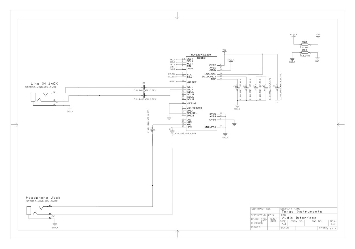
    I used CC85XX headset reference design 1_3_SCHEMATIC.pdf as reference :

    I checked with evaluation board's schematic and chip's documentation's schematic but didn't see big difference.

    For the power up sequence, regarding I use LDOIN, there is nothing to do, I use the same power source.

    Is there any hardware difference between DAC mode and ADC mode? I can't see that.

    Thank you for your concern

  • Hi, Frederic,

    Please take a look at the script file below. It is made to configure the evaluation board with the same schematic that you are using. This script configures the AIC3204 in recording mode:

    2630.MIC_to_DOUT.txt
    ###############################################
    # High Performance Stereo Recording
    # ---------------------------------------------
    # PowerTune mode PTM_R4 is used for high
    # performance 16-bit audio. 
    #
    # IN3L/R is routed to the LADC/RADC in a
    # single-ended manner.
    ###############################################


    ###############################################
    # Software Reset
    ###############################################
    #
    # Select Page 0
    w 30 00 00
    #
    # Initialize the device through software reset
    w 30 01 01
    #
    ###############################################


    ###############################################
    # Clock Settings
    # ---------------------------------------------
    # The codec receives: MCLK = 12.288 MHz,
    # BLCK = 3.072 MHz, WCLK = 48 kHz
    ###############################################
    #
    # Select Page 0
    w 30 00 00
    #
    # NADC = 1, MADC = 2
    w 30 12 81 82
    #
    ###############################################


    ###############################################
    # Signal Processing Settings
    ###############################################
    #
    # Select Page 0
    w 30 00 00
    #
    # Set the ADC Mode to PRB_P1
    w 30 3d 01
    #
    ###############################################


    ###############################################
    # Configure Power Supplies
    ###############################################
    #
    # Select Page 1
    w 30 00 01
    #
    # Power up AVDD LDO
    w 30 02 A9
    #
    # Disable weak AVDD in presence of external
    # AVDD supply
    w 30 01 08
    #
    # Enable Master Analog Power Control
    # Power up AVDD LDO
    w 30 02 A1
    #
    # Set the input power-up time to 3.1ms (for ADC)
    w 30 47 32
    #
    # Set the REF charging time to 40ms
    w 30 7b 01
    #
    ###############################################


    ###############################################
    # Recording Setup
    ###############################################
    #
    # Select Page 1
    w 30 00 01
    #
    # Route IN1L to LEFT_P with 20K input impedance
    w 30 34 80
    #
    # Route CM1L to LEFT_M with 20K input impedance
    w 30 36 80
    #
    # Route IN1R to RIGHT_P with 20K input impedance
    w 30 37 80
    #
    # Route CM1R to RIGHT_M with 20K input impedance
    w 30 39 80
    #
    # Enable MICBIAS
    w 30 33 40
    #
    # Unmute Left MICPGA, Gain selection of 6dB to make channel gain 0dB
    # Register of 6dB with input impedance of 20K => Channel Gain of 0dB
    w 30 3b 0c
    #
    # Unmute Right MICPGA, Gain selection of 6dB to make channel gain 0dB
    # Register of 6dB with input impedance of 20K => Channel Gain of 0dB
    w 30 3c 0c
    #
    # Select Page 0
    w 30 00 00
    #
    # Power up LADC/RADC
    w 30 51 c0
    #
    # Unmute LADC/RADC
    w 30 52 00
    #
    ###############################################

    Best regards,
    Luis Fernando Rodríguez S.

  • Hi,

    It's a little better, cutoff are shorter. So it seems that the problem is within the configuration but it's not a normal behavior.
    Maybe I have to let LDOIN and try with external avdd?
  • Hi, Frederic,

    Could you try with the external power supplies, please? The audio codec is sensitive to power supplies. This could affect the ADC and DAC behavior directly.

    Additionally, have you tried your application in playback mode? I mean, is this problem only related to the ADC or do you have same problems on the playback? Could you try with a bypass mode? You may try it to route the analog input directly to the output.

    Best regards,
    Luis Fernando Rodríguez S.
  • Hello,

    Thank you for thoses advises,
    I can't do hardware work until monday but I will do it as soon as I can.
    When you say in playback mode you mean in DAC mode? I had no problem in DAC mode.
    I will try to bypass first to see what happen before applying external supplies.

    I saw on an other post that someone fix a similar issue by adding delay (1000 ms), can it be a solution for me? where can I put this delay?

    thank you again, I will contact you on monday, have a good week end.
  • Hello, Frederic,

    Yes, I would mean the DAC mode. If you don't have any problem with the DAC section and playback mode, I would recommend to try with the loopback modes in the TLV320AIC3204. In that way you may send the ADC data to the DAC input and verify the result in the codec outputs.

    Regarding the delay that you mentioned, we only recommend to add delays in several cases:
    - After hardware/software reset. The device takes 1ms to get initialized.
    - After PLL is powered up. The device requires 10ms to be initialized.

    Best regards,
    Luis Fernando Rodríguez S.
  • Hello Louis,

    Sorry for the late reply,

    I'm not able to do the loopback working :

    I put this line w 30 1d 01 after power up dac and adc but I don't get any sound.

    What do I miss?

    thank you

  • Hi, Frederic,

    I think that you are configured the wrong bit. Could you try with the digital loopback (line below)?

    w 30 00 00 (page 0 selected)
    w 30 1d 10 (D4 - digital loopback)

    Best regards,
    Luis Fernando Rodríguez S.
  • Hi,
    Yes, I didn't see that the register settings were on two pages.
    But even with the good configured byte I don't get any sound out. I can hear the powering pop but that's all.
    I made an other board with an other chip and I have so much less cutoff, it's strange, the only difference is that I use a classic dc-dc converter while the first board use an isolated dc-dc converter. Maybe I have a ground issue, because with the classic converter I grounded with the usb shield, maybe the isolated converter ground is too weak? but no matter for the dac..
    I have to test with external supply too.
  • Hi Louis,

    I tried with external supply and unfortunately it's the same behavior...
    I'm completely lost at this point.
    I don't know where come from the problem.

    Any new idea?
    thank you

    edit: something strange again, if I connect general ground supply (3.3V) with the external ground supply (1.8V) I get very few cutoff. It's definitely a ground issue, but what kind?

  • Hi, Frederic,

    Is MICBIAS being connected to GND? In your schematic seems to be connected in that way. MICBIAS is actually a configurable output. So, it may provide a 2.0V, 2.5V or AVDD voltage. Could you try disconnecting this pin? You may leave it floated if it is not in use.

    Let me know if the problem persists.

    Best regards,
    Luis Fernando Rodríguez S.
  • Hi,
    Thank you for your reply.
    Sorry, this was a previous design ; current design has micbias left floated, the problem is somewhere else.
    Thank you for your help