This thread has been locked.

If you have a related question, please click the "Ask a related question" button in the top right corner. The newly created question will be automatically linked to this question.

PCM1794A: Low frequency drift with static levels

Part Number: PCM1794A
Other Parts Discussed in Thread: PCM1794, LME49720

Hello,

 I can observe a low frequency drift (~1Hz) at the output of the current to voltage converter differential  stage, it is proportional to output voltage, amplitude is roughly 1 part per thousand ( 5mV at 5V output). I tried to investigate around power supplies, but I did not see any low frequency noise. I  just see Vcom is not stable although there is a 47UF capacitor here, I measured  2.192V but with 0.8mV slow change, and I guess it can act with Iout as well.

 Have you any exoerience with low frequency  noise (drift) on PCM1794A like this ?

Thanks

  • Hi, Daniel,

    Welcome to E2E, Thanks for your interest in our products!.

    Sorry for the delay, my colleague in charge of this device has been quite busy lately. This is not a common issue. The variation you see in VCOM is similar to the described low frequency drift?

    Best Regards,

      -Diego Meléndez López
       Audio Applications Engineer

  • Hi, Diego,

     Thanks for your answer, yes its looks VCOM is not stable with a low frequency drift, but I have no idea of the reason as power supllies are ok. How is  Vcom made internally ?  I do not see INL or DNL specification with PCM1794A, what can I expect ?

    Best regards.

    Daniel

  • Hi, Daniel,

    VCOM should be independent of the power supply because it is generated by an internal constant source, and it should have a value of 2.5V at all times. The issue might be related to a current leak in the capacitor, You might disconnect the decoupling capacitor and check the VCOM level looking for any variation. Vcom variation spec is not tested because it is only used as an internal reference for the operation of the device.

    Best Regards,

      -Diego Meléndez López
       Audio Applications Engineer

  • Daniel - According to the datasheet (figure 31) those bypass capacitors connect in an odd way from pins 21 and 22 to VccL and VccR rather than connecting to ground in the more conventional way. Why this is done I have no clue: The datasheet does not say why.

    The PCM1794 EVM (figure 2-4) also shows the VcomL and VcomR pins' bypass caps referenced to Vcc. The EVM however shows CA3 (another bypass) with reversed polarity which is clearly an error.

    Is it possible that in layout they could have gotten referenced to ground and/or installed with reverse polarity? Pins 21 and 22 should (according to the datasheet at least) connect to the caps' "-" terminals with the positive terminals connecting to VccL and VccR. That gives them about +3V of terminal voltage. If they got referenced to AGnd by accident they will be reversed-biased by about -2.2V.

    This is just my best guess. Good luck and please let us know what you find.

    Wayne

  • Diego and Wayne,

    Thanks for your answers.

    Diego, you said 2.5V expected at VCOM, but I have 2.2V only, do you have an idea why, there is no spec in datasheet about Vcom.

    Regarding VCOM decoupling,  I use X5R 47U capacitors to VCC, I tried to add capacitors to AGND without change. I guess a bigger capacitor value is not a problem for Vcom, but I still have to try without.

    Regards

    Daniel

  • Hello Diego,

    We have measured this VCOM on multiple parts on the same conditions (47uF directly to analog 5V) and they also range from 2.2 to 2.7V, does this "irregularity" (compared to your previous post stating that it should be 2.5V) change the noise performance or degrades functionality/MTBF in any way?

    Best regards,
    Théo

  • Hello,

    I am bumping this thread because it has been idle for almost a month without a TI answer.

    We have conducted additional tests on the device. VCOM seems to vary with a "random noise" that influences the output static level. It is still between 2.15 and 2.5V depending on the output level and if the clocks are present. Like said in the first post this seems to create a noise for around 1mV/V after our amplification stage, which is VERY problematic for the client and for calibration purposes.4

    The noise seen on VCOM seems to be correlated with the noise seen on the output. Using 2 synchronized digital multimeters we measured both values at the same time. When the value on VCOM decreases, the output value inecrases significantly and vice versa.

    Can we get some feedback ASAP on the importance of this value (which must stay at 2.5V at all times according to your post), and it's effect on the multiple chip parameters, especially for the noise?

    Thanks in advance

    Best regards,
    Théo

  • Hi Diego,

    Let me introduce myself : Pol Martinot, Senior Apps MixSignal Engineer @Mu-Test.
    Apparently, we have narrowed-down the Low Frequency noise on the outputs, to be strongly correlated with variation of VCOM.
    You mention that VCOM should present stable voltage @2.5V; can we somewhat "impose" 2.5V to VCOM pins ? ie. would design of PCM1794A support this ? (eventually thru resistor for protection ?)
    Thanks in advance for input,
    Regards
    Pol.
  • Hi, Pol,

    Welcome to E2E!

    Sorry for the delayed response. My colleague and I are investigating this issue with the team. Regarding your question, adding an external circuitry for the VCOM pins might not be good as any external variation in this pin will affect the performance of the device. We expect to get an update on this particular issue by next week. 

    Best Regards,

      -Diego Meléndez López
       Audio Applications Engineer

  • Hi Diego,

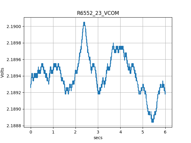
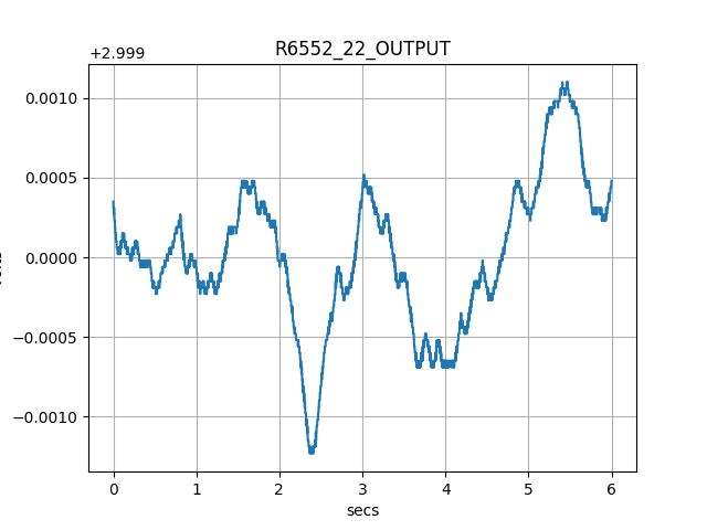
    I am glad to hear you again. As you can see, we continue to investigate around VCOM as it looks to be the cause (or the image) of the  noise we observe, please see the picture, this is the ouput of the I2V converter stage, after Iout. p-p variation is 5.6mV, although DAC input is steady. Second picture is VCOM noise.

    How VCOM is generated internally, any schematic or detail will help.

    Best regards.

    Daniel

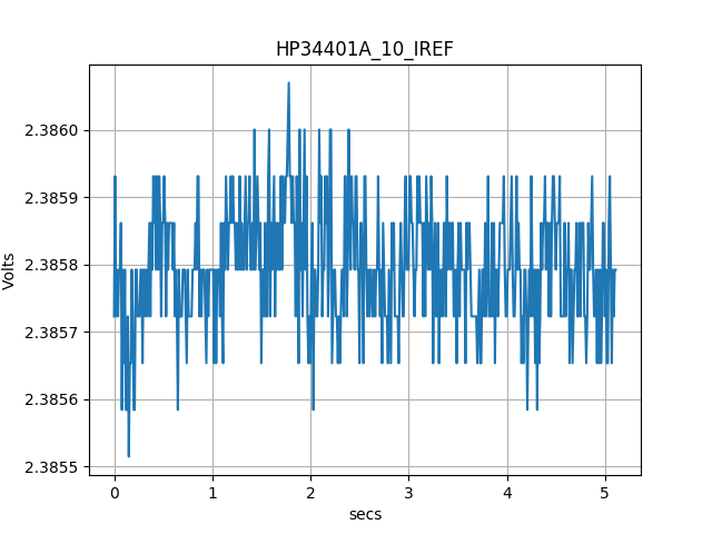
  • They are pictures of the measurements we did on VOM, IREF and Vout (after the I2V AOP),  PCM1794 input is a static value around full scale.

    Vout noise is following VCOM exactly..

    Best regards

  • Hello,
    It has been a few months since this issue has been opened now and we would be interested in solving this problem.
    Could you please share with us your team's conclusion on this matter?

    Best regards,
    Théo
  • Dear TI representatives,

    We have conducted several tests on this matter.

    1) We forced the VCOM pin to 2,5V with a MAX6033 through a low value resistor. This reduces the output noise from about 1mV/V to 0,6mV/V and improves significantly the spectral purity of the signal on the output. We believe that the rest of the noise is inherent to the functionality of the chip (sigma-delta). This solution, however, seems to degrade dynamic performance @ 20kHz and higher.

    2) We have modified our design to put ourselves in similar condition to this post e2e.ti.com/.../104330 . That helped in some ways, but not for the output 1/f noise. However, we seem to have 103Hz intermodulation appearing around the fundamental when we drive a sinusoid with the DAC, @ all frequencies.

    3) We verified that the problem was not thermal as detailed here : e2e.ti.com/.../262779 . Adding a very good dissipator does not seem to help the issue, as the component was already quite well ventilated, constantly.

    Therefore, I would like to ask these additional questions :

    According to Don Dapkus' post, there is, or used to be, problems on the VCOM pin on other components of the same family. e2e.ti.com/.../1301768 Do you have more details to share?

    Is forcing the VCOM pin an acceptable and possible workaround according to you? Would you recommend other solutions to reduce this output "very low frequency" noise that has a repercussion on dynamic performance? The goal is to improve DC accuracy and spectral purity.
    Alternatively, are there ways to disable the internal current generator used for VCOM inside the chip, on the PCM1794A?

    Could you confirm the 103 Hz intermodulation seen on point 2 is or is not internal to the chip? This intermodulation is not observed at the output of the I/V converters, but it is observed after the subtractor, at about -117dBc from the fundamental. This is independant from the original issue, and "forcing VCOM to 2.5V" does not change the behaviour observed.

    Best regards,
    Théo
  • "However, we seem to have 103Hz intermodulation appearing around the fundamental when we drive a sinusoid with the DAC, @ all frequencies."

    I saw this and had to jump in. The 103 Hz intermodulation may not have anything to do with your 1/f noise on Vcom but:

    Is there a DECT cordless telephone or base unit anywhere near the DUT? 100 Hz is the idle channel bearer rate that the base transmits to ping handsets.

    I've experienced a similar 100 Hz RF envelope rectification by the LME49720 from a US DECT 6.0 base station that was over 8 feet away. You may not be using the LME49720 in the I-V stage but there may be a similar EMI susceptibility. FWIW no other dual op amp I tried had the high degree of susceptibility.

    The discussion begins here and goes on for a couple of pages: www.diyaudio.com/.../205304-low-distortion-audio-range-oscillator-692.html

  • Hey Wayne, Thanks for your message. The thread on diyaudio provides valuable information.

    We have DECT cordless phones, but they are more than 10 meters away from the DUT. However, the intermodulation is a precise 103.1xx Hz. We don't see this intermodulation at the output of the I/V converter, but we see it at the output of the AD797 we use as a substractor, which we found intriguing and problematic as we thought it came from the DAC.

    (According to the topic the issue is mostly specific to the LME49720 but we do not use it in our design. Furthermore the multiple OPA16xx we use seem to be unaffected by this EMI issue, or they at least are buried in the noise floor... This confirms your data.)

    If this is in fact an EMI issue it will greatly simplify our problem, and we'll just add shielding.

    We will attempt more tests on monday with a decent shield. Thanks again for the heads-up.