This thread has been locked.

If you have a related question, please click the "Ask a related question" button in the top right corner. The newly created question will be automatically linked to this question.

TLV320AIC34: TLV320AIC34 in TDM Mode

Part Number: TLV320AIC34

As a part of my university project I was trying to use Texas Instrument's TLV320AIC34 for receiving an 8 channel Time Division Multiplexed ( TDM ) signal sent from another CODEC and trying to capture it from 4 different TLV320AIC34s with different offset. However, before doing 8 channel directly I was trying out the same with 2 channel data using a single TLV320AIC34.

Using CRO, I am able to track that Data Input, D1 is getting the valid signal however I cannot get the audio at Head Phones. Should I make some other configurations?

I have made these configurations :

Master Clock, MCLK = 9.6 MHz

Bit Select Clock, BCLK = 12.288 MHz

Word Clock, WCLK = 48 kHz

Data Offset = 0

Clock Configuration  from AIC34 GUI:

PLL Enbaled

Clock Source : MCLK

P = 1

K = 10.24

R = 1

CODEC Clock Output : PLL Output

Audio Interface Configurations from AIC34 GUI:

16 bits data

DSP Mode

256-clock bit mode

  • Hi, Jithin,

    Welcome to E2E and thank you for your interest in our products!

    Could you provide your entire registers configuration in order to have a better approach to this issue, please? Additionally, is the codec configured in master mode (BCLK and WCLK as outputs and generated by the codec) or slave mode (BCLK and WCLK as inputs and sent from another device)?

    Thank you!

    Best regards,
    Luis Fernando Rodríguez S.
  • Hey Luis,

    In "AIC34" software, I have made the above changes only and the rest of the configurations remain the default configurations. Being a novice, I am not much aware what all register configurations you want to know. Can you please give me a bit more insight into it?

    Regarding master-slave mode, I am using the Codec as a Slave with MCLK, BLCK and WCLK fed from external device.

    Thank You
    Regards,
    Jithin
  • Hi, Jithin,

    I recommend to ensure that all the analog inputs and outputs are correctly enabled. You may see in the AIC34 software that the analog inputs can be routed to the ADCs and they need to be un-muted. Then, you need to adjust the gain and enable the ADC. Once the ADC is enabled, you should see data values at the DOUT pin.

    Then, the DACs must be routed to the line and/or headphone outputs. Similarly, the outputs need to be enabled and un-muted.

    Best regards,
    Luis Fernando Rodríguez S.
  • Hi Luis,

    Thanks for your reply.

    The data that I am sending to TLV320AIC34 is a digital signal only, not an analog one. Also, I have tried to send 2 channel data in I2S mode with TLV320AIC34 acting as a slave as well as a master, and in both case I was able to receive the signal at my head phones. But now when I am trying to do it in TDM mode it's not working. Can you suggest some probable faults?

    Thank You
    Regards,
    Jithin
  • Hi, Jithin,

    In the TLV320AIC34, the TDM mode works at 256-clock mode (see page 0 / register 9 for details). You would need to have a BCLK = 256*fs = 256*WCLK. In master mode (BCLK and WCLK as outputs), BCLK and WCLK are configured automatically.

    Then, you would need to configure the DOUT and DIN pin in high-impedance for non-valid data (see page 0 / register 8 for details). Finally, in TDM mode it is required an offset in order to match with the specific channel data. This offset can be configured with page 0 / register 10.

    Please try all these configurations and let me know if you require additional assistance.

    Best regards,
    Luis Fernando Rodríguez S.
  • Hi Luis,

    Sorry for the late reply.

    I have some issues regarding MCLK in TLV320AIC34.

    1. Is MCLK necessary in TDM mode operation? If so, is there some other configuration changes to be done like P, K, R values or enabling PLL etc.?

    2. I tried to probe the input data in CRO, which seems to be perfect, however when I try to interface the data lines with TLV320AIC34 and probe it to CRO it gets distorted.

    3. Also when I try to connect 9.6MHz MCLK, even though BCLK and WCLK are configured as input, still the TLV320AIC34 board seems to generate it's own BCLK and WCLK when it is not provided as input. 

    Maybe there is some fault on my side, but can you please help me out if you had some similar experience or have some idea about whats going wrong.

    Thank You

    Regards,

    Jithin

  • Hi, Jithin,

    In all our audio codecs, it is required an input clock called CODEC_CLKIN to get the DAC_fs and ADC_fs. This CODEC_CLKIN is generated from either MCLK, BCLK or GPIO2 as shown in the Audio Clock Generation Processing picture ( www.ti.com/.../tlv320aic34.pdf ).

    The default register configuration divides the MCLK by 256. For example, if you need a DAC_fs and ADC_fs = 44.1KHz, you would require to use a MCLK = 256*44.1KHz = 11.2896MHz. Otherwise, you would need to use the Q divider path or the PLL path to get the desired sampling rate.

    Even in TDM mode, you would require a CODEC_CLKIN to generate the sampling rate.

    The TLV320AIC34 only generates BCLK and WCLK pulses when these pins are configured as outputs. If these pins are generating the pulses, then they could be configured in master mode or probably any other component is sending the I2S clocks to the audio codec.

    Best regards,
    Luis Fernando Rodríguez S.
  • Hi Luis,

    Thanks for your reply.

    As you mentioned, I have provided CODEC_CLKIN using BCLK = 12.288 MHz and Q = 2, which makes CODEC_CLKIN = 12.288/256 MHz = 48kHz, which is my desired sampling frequency. But still I am not able to get the output.

    Is there any pin from where I can probe DAC_fs and ADC_fs to ensure whether ADC and DAC are getting correct sampling frequency? Or, is there any other pin that I can probe and figure out the fault?

    Thanks,

    Regards,

    Jithin

  • Hi, Jithin,

    The only way to verify if the DAC_fs and ADC_fs are correctly getting the proper sampling frequency is with the WCLK pin. You would need to configure the codec in master mode. Once the ADC and DAC are enabled, the WCLK should start generating the ADC_fs.

    Best regards,
    Luis Fernando Rodríguez S.
  • Hi Luis,

    Thanks for your reply.

    The 8-channel TDM mode operation seems to work fine when I am providing audio signal from external device.

    Now I am trying to send audio signal from TLV320AIC34 and capture the same. For that purpose can you tell me how to use microphone in TLV320AIC34 and how to configure it? Also, can you please share a schematic diagram of the board?

    Thanks,

    Regards,

    Jithin

  • Hi, Jithin,

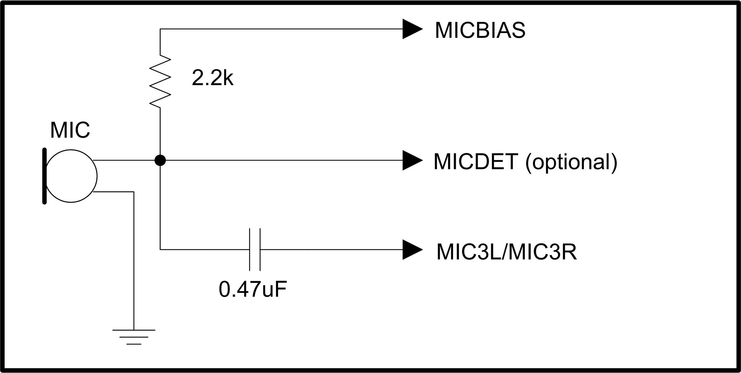
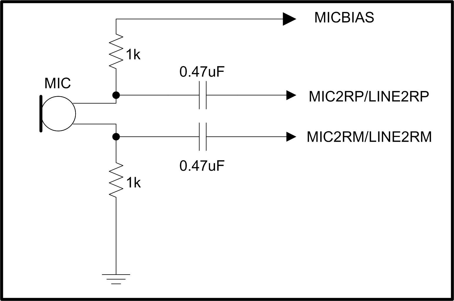
    In order to use the microphone, you would need to verify if it will be single-ended or differential. Each microphone require of a particular configuration as shown below:

    Single-ended microphone configuration

    Differential microphone configuration

    Then, you would need to configure the appropriate registers to route the selected analog inputs to the left or right ADC channel (page 0 / registers 17-24). Additionally, the MICBIAS level must be adjusted depending of the microphone requirements (page 0 / register 25).

    Best regards,
    Luis Fernando Rodríguez S.

  • Hi Luis,

    Thanks for your reply.

    Can you tell me what all configurations are needed to be done in order to use the on-board microphone of TLV320AIC34?

    Thanks,

    Regards,

    Jithin 

  • Hi, Jithin,

    Please take a look at the attached script. I contains the register code used to configure the on-board microphone on the TLV320AIC34EVM. The code lines are in format w (write) 30 (I2C address) xx (register address) yy (register data).

    On_board_mic.txt
    ##############################################################
    #
    # On-board MIC to ADC
    #
    # Digital audio setup for operation with defaults of USB-MODEVM
    #
    # Input:
    # EVM microphone (MIC3L/R inputs)
    #    - Volume control = 0dB (not muted)
    #    - MIC3L connected to LADC
    #    - MIC3R connected to RADC
    #    - MICBIAS = 2.5V
    #
    # Ouput:
    #
    # ADC
    #    - LADC ON
    #    - RADC ON
    #    - PGA gain = 0dB
    #    - Output amplifier gain = 0dB
    #
    ###############################################################
    #
    w 30 11 0F
    w 30 12 F0
    w 30 16 7C
    w 30 13 7C
    w 30 0F 00
    w 30 10 00
    w 30 19 80
    

    Best regards,
    Luis Fernando Rodríguez S.