This thread has been locked.

If you have a related question, please click the "Ask a related question" button in the top right corner. The newly created question will be automatically linked to this question.

TLV320AIC3204: TLV320AIC320 IN1 Problem

Part Number: TLV320AIC3204

Hello, TI Experts,

Our customer sent us a question about TLV320AIC3204's IN1 channel cannot input the input signal.

We have done these tests:

1.delet the components connected to the IN1 Channel, not make sense

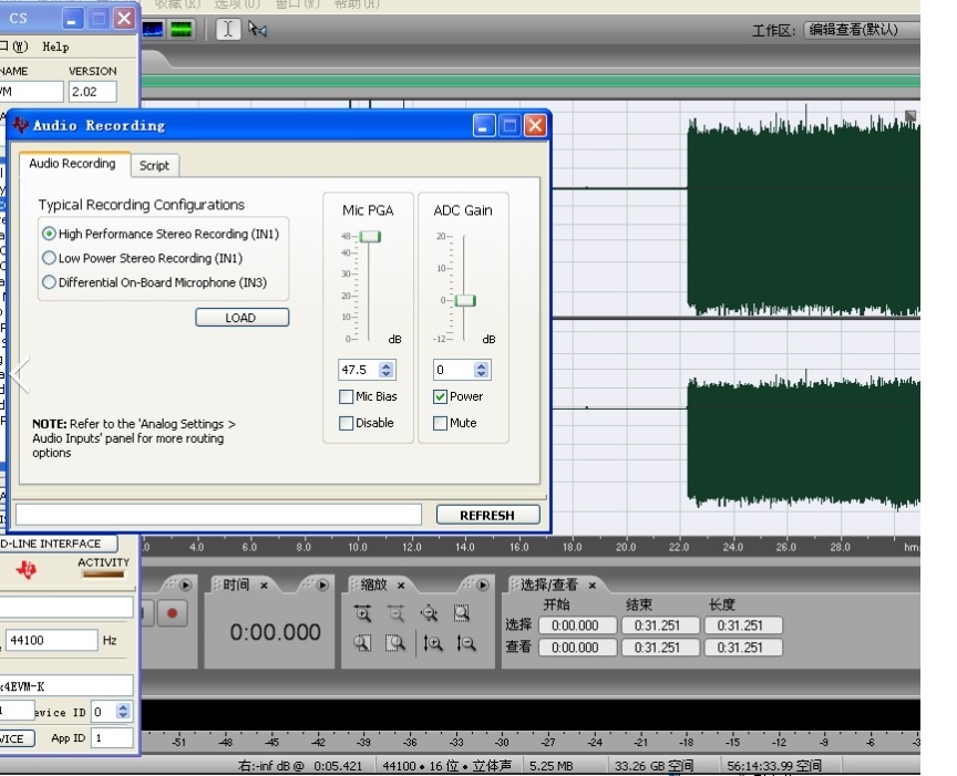
2. set the gain between input to ADC to 0dB,then analyse the ADC‘s data by recording on customer's computer,we found ADC's output I2S is strange.Its DC reference level is not 0V,but offset to the negative end.

When set the PGA gain to 0dB,dc offset is -48dBV(around 4mV);Then increase PGA gain,The reference signal move downward;

When set the PGA gain to the max 47.5dB,the signal reference will be -24dBV(around 0.06V)

3. We change the channel to IN2/IN3,the offset is much smaller.

The Question Is:

Why is  IN1  different from IN2/IN3?

Our Customer has designed to use IN1,if change to IN2/IN3,It may spend much more time to redesign.

Do we have any methods to solve the IN1 problem?

Look foward to your kindly reply,Thank you ~~

  • Hi, Fang,

    Welcome to E2E and thank you for your interest in our products!

    Could you provide the complete registers configuration and the AIC3204 schematic portion? There's no difference between IN1, IN2 and IN3. So, there should be a mistake on the configuration.

    Best regards,
    Luis Fernando Rodríguez S.
  • Hi Luis:

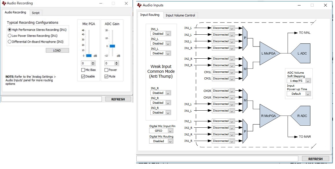
    We do the test with AIC3204EVM and it's GUI, using the  recording setting recommended by the GUI, just change MIC PGA Gain and Mic input channel. The IIS is analyzed by PC software, such as Audition or Goldwave. 

    1, We use IN1 as Mic input channnel. When set the PGA gain to 0dB, DC reference voltage is -48dBV(around 4mV);Then increase PGA gain,The DC reference level move down.When set the PGA gain to the max 47.5dB,the signal reference will be -24dBV(around 0.06V). In this case, customer's algorithm it is difficult to adjust with a indeterminate DC reference voltage.

    2. We change the Mic input channel to IN2, change PGA Gain from 0dB to 47.5 dB, the DC reference voltage just change a little.

    3.We change the Mic input channel to IN3,do the same test, change PGA Gain from 0dB to 47.5 dB,  DC reference voltage is stable, the variation is very very small.

    Use Input routing to change Mic input channel. (IN1/IN2/IN3)

  • Hi,

    The offset issues are commonly seen in the audio codecs due to the delta-sigma activity. In order to reduce or eliminate them, I recommend to use the IIR or biquad filters of the AIC3204 processing blocks. The filters may be configured as a high-pass filter at 80Hz. You would only need to configure the filter coefficients to make it. Our TI biquad calculator tool may be used for this purpose:

    www.ti.com/.../COEFFICIENT-CALC

    Best regards,
    Luis Fernando Rodríguez S.
  • Dear Luis:

    Thanks for your Kindly and quick reply.

    Set a high-pass filter to remove the DC component, It maybe effective. But, how can I set a ADC filter in AIC3204? Could you please kindly give some comments?

    We can get five coefficient with TIBQ tool, but I don't kown how to use them to make a ADC filter. The AIC3204 GUI just show us DAC filter(EQ/Shelf).

    Best regards!
  • Dear Luis:

    Add a question:

    The offset issues are commonly seen in delta-sigma ADC, so what caused the different offset performance in different channels?

    As we kown, only IN1 can bypass direct to analog output, is there any relation?

    Best regards!
  • Hi,

    You would need to use the coefficients in the respective IIR filter registers. The TIBQ tool will give you three coefficients (N0, N1, D1). These coefficients need to be configured on page 8, registers 24-34 or page 9, registers 32-42. For more details, please consult the First-Order IIR section ( www.ti.com/.../slaa557.pdf ). You would need to use the command-line interface of the GUI to configure the registers by command lines.

    In some cases, the analog inputs have optional or alternative functions that may affect the signal performance. Since the IN1 can be bypassed to the output, it may be affected as you mentioned.

    Best regards,
    Luis Fernando Rodríguez S.