This thread has been locked.

If you have a related question, please click the "Ask a related question" button in the top right corner. The newly created question will be automatically linked to this question.

PCM1861: ADC PCM1861 do not generate LRCK and BCK in Master Mode

Part Number: PCM1861

Hi, 

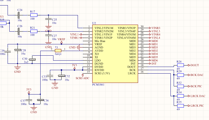
ADC PCM1861 don't generate LRCK and BCK in Master Mode. I used CMOS Clock generator 3.3V 24.576MHz, configured pins according to datasheet : Master Mode 256fs MD1=1 MD0=1. I check connection already and all looks properly. VREF is 1.6V LDO=1.8V. On inputs is reference voltage 1.6V . I don't have any idea what's wrong. '

It is my circuit:

please help me

  • Hi, Dominik,

    Welcome to E2E, Thanks for your interest in our products!.

    The schematic section available seems correct, my only recommendation would be to place the decoupling caps of AVDD closer to the device, and after the ferrite. 

    Can you please share the complete configuration of all the hardware configurable pins of the PCM1861?. Also, how are the unused input pins terminated?

    Best Regards,

      -Diego Meléndez López
       Audio Applications Engineer

  • Configuration of all h/w pins looks like this:
    MD6=0
    MD5=0
    MD2=1
    MD4=0
    MD3=0
    MD1=1
    MD0=1

    Unused input pins are connect directly to goldpins.
    Thank you for reply
  • Hi, Dominik,

    Thanks for the reply. The configuration is correct, so the device should be streaming audio content once a proper master clock signal is provided. I have verified this setting on the EVM and the device is operating as expected with the given input MCLK and HW configuration. Have you tried using a different MCLK source to verify that the MCLK signal is valid?. Also, do you have the option of changing the IC to try a new one, just in case the DUT is damaged?

    Thanks and Best Regards,

      -Diego Meléndez López
       Audio Applications Engineer

  • I replaced MCLK already. At first i used another clock source : CMOS oscilator 49,152MHz and it didn't work. Later I replaced clock source to 24,576MH CMOS oscilator and still not work. MCLK signal reaches to the SCLI pin, I checked it on oscilloscope.  I don't have the option of changing IC by the new one, but if will necessary I'll buy new one. Today I measured a state on all pins in my colleague similar device (he used the same PCM in his project) and voltage on all pins were the same like in my ADC) but his ADC work properly, generate LRCK and BCK signals.

  • Hi, Dominik,

    Thanks for the feedback. Then it seems the IC having some issues. I would recommend you to request a sample and try with a new device in your board. You might also check for any possible short in the board, particularly in the clocks section. 

    Best Regards,

      -Diego Meléndez López
      Audio Applications Engineer

  • HI,

    Today I tried to fix the problem with ADC still and it started working. I unsolder a capacitor 1u at Master Clock generator (before I using two capacitors: 1u and 100n). I unsolder enable resistor at ganerator (1-work, 0-not generate, no connect - work). I took off all jumpers at DAC configuration (I have also DAC in my project but it isn't on PCB no yet). Later I checking a LRCK and BCK signals using logic analyser. And finally I disconneted the power supply plug  for a moment and then ADC start to work properly.

    I also noticed that when I disconnect the plug power supply for longer time (even 5 seconds) the ADC don't work properly, LRCK and BCK is disable. But when I disconnect a plug for a moment - ADC work properly. It is weird. When I back home from university, I decided to exchange oscilator to 49,152MHz. When I did it the ADC stoped work properly. I tried all sequences like before, but ADC still not work. I decided to exchange oscilator back to 24,576MHz. I did it and then ADC don't work. I trying to use another source of power, connent directly behind the power section on PCB, without any effect. I tried resolder oscillator, capacitors near, capacitors at power section, without any effect. I tried also turn off oscillator (using eneble pin to ground), turn on power, and turn on oscillator - without any possitive effect. I attach whole the circuit of my PCB below.

    Maybe exist special procedure of starting this ADC?

    schemat2.pdf


    EDIT (next day):

    today I turn on my PCB and it started working, but I don't know the reason still. The procedure with power supply reset work today but PCM don't generate LRCK and BCK signals until I connect third wire, between DOUT and logic analyser. Where is the problem? Sometimes work properly but somtimes don't work at all.

    EDIT 2 (same day):

    It has started work properly when I short XI pin to ground, ADC generate all signals directly after plug power supply.