This thread has been locked.

If you have a related question, please click the "Ask a related question" button in the top right corner. The newly created question will be automatically linked to this question.

PCM1796: feeding TPA3255 with balanced signal

Part Number: PCM1796
Other Parts Discussed in Thread: TPA3255, , OPA1612, OPA1678, OPA1632, TINA-TI

Hi TI experts,

I would like to feed TPA3255 directly from PCM1976 with balanced signal - PCM1796 has balanced output and TPA3255 has balanced input, so it should work well ;) Could you give me some examples how to connect them together to get best audio results?

Thanks, Tomasz

  • Hi Tomasz,

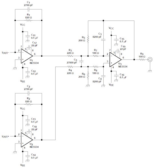
    Figure 35 has a good example, as you do not need the final amplifier stage as shown in figure 36. We have some great amps that can be used for this application, I recommend the OPA1678. You should favor thin film surface mount resistors and NP0/C0G type capacitors for the discrete components. You will also need a DC blocking capacitor, as the output of the amps will have a negative bias voltage, while the input of the TPA will have a positive bias. A large electrolytic cap would serve this purpose. At the very least a passive RC low pass filter should be implemented as well. This can be on the output of the OPA1612, though note you may need to account for the resistance in the gain calculation.

    Thanks!
    Paul

  • Hi Paul,

    Thank you for your replay but I didn't get it... Did you mention the circuit:

    The circuit shows unbalanced implementation - I need balanced/symmetrical signal on the output to feed balanced input of the TPA3255

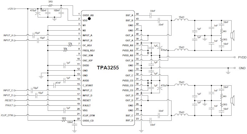
  • Here is the TPA3255 stereo BTL implementation example:

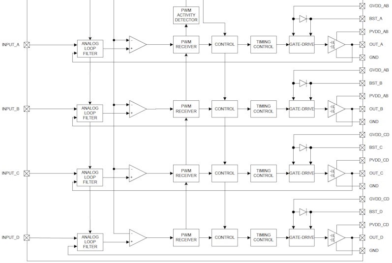
    The INPUT_A and INPUT_B control two separate amplifiers working in bridge mode (BTL):

    To optimally use the amplifier I need symmetrical/balanced input audio signal... The PCM179x DACs have balanced current output but typical application like in datasheet converts the balanced signal to unbalanced using operational amplifier. The amplifier provides balanced-to-unbalanced conversion and filter functionality combined. Have you got any example hot to implement the output filter without converting signal to unbalanced?

  • Hi Tomasz,

    I was referring to figure 35.

    In this case you would not implement the differential to single ended conversion, and instead connect it to your class D amplifier.  This would provide the I/V stage while still being differential.

    You could still have a RC low pass filter right at the input:

    Thanks!

    Paul

  • Hi Paul,

    OK, so you would suggest not implementing low pass filter after the DAC at all?
    What will be the out of the audio band noise without post low pass filter after the DAC???

    In this case I would have some questions:
    1. Do I need a low pass filter after Delta-Sigma Audio DAC at all? If yes, than why, for what reason? If no, why it is suggested in datasheet?
    2. What influence has the output filter on audio performance - THD+N, residual noise etc...

    I would really like to get full performance out from the DAC :)
  • Hi Tomasz,

    There is actually two low pass filters in the design.  The first is in the feedback of the amp, and the other would be an RC on the input.  The most aggressive what to remove OoB noise is to introduce another multiple feedback LPF.  I have created a TINA model for you as well.

    Thanks!

    Paul

    PCM1796 Diff-out.TSC

  • Also, I recommend the OPA1612 for the first stage, as it is a low noise bipolar input amp. The second stage is the OPA1678, which is a low noise FET input amplifier. The FET input reduces the current noise on the input, which is good as this stage has the high value resistors .

    Thanks!
    Paul
  • Hi Paul,

    this is indeed a very good idea :) why I didn't simply think using two separate opamps... the simplest solutions are usually hard to see.
    I have just one concern now - you use in your design very high value resistors. Would it not be better to keep original design with low resistor values to keep low noise level? Just put two opamps...

    Thanks!,
    Tomasz
  • Hi Paul,

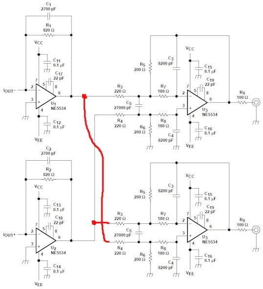
    would it be possible to simple duplicate the last output stage out of phase like this:

    so I can drive positive and negative input of the TPA3255 with 180deg phase shift. What do you think about it?

    Cheers, Tomasz

  • For the first stage I/V I can use your recommended bipolar input OPA1612 amplifier, and for the second stage the OPA1678 :)
  • Hi Tomasz,

    Your design would also work well.  As far the resistors are concerned, this will be a balance between power and noise.  I think you should be fine with lower values.

    Thanks!

    Paul

  • Hi Paul,

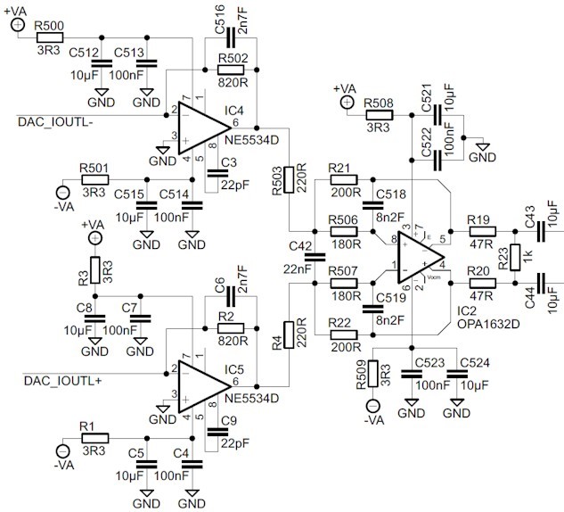
    thank you for your replay. I thought about it one more time and have other idea :) What do you think about using fully-differential audio operational amplifier like OPA1632? I redraw the output stage using OPA1632:

    What do you think? Is it a best option for optimal audio performance?

    Cheers, Tomasz

  • maybe I can additionally replace the I/V stage with OPA1612 like you suggested...
  • Hi Tomasz,

    I think it would be a good option to try the FDA. Though it would be interesting to put them both into TINA-TI and simulate the noise. I still think it would be comparable. As far as a sound quality difference is concerned, that may be more of an opinion. With the two amp solution you can try a few different devices, but I think as long as you have the 2nd order filter you should have a high quality input for your TPA3255.

    Thanks!
    Paul
  • Hi Paul,

    I will try to simulate both however I placed the FDA already in the schematic diagram - I have great experience with OPA1632. Design should be ready in 1-2 weeks. Next 3 weeks layout and in 5 maybe 6 weeks I should have first modules on my desk :) If you like I can share the results with you Thanks for your support!

    Cheers,
    Tomasz