This thread has been locked.

If you have a related question, please click the "Ask a related question" button in the top right corner. The newly created question will be automatically linked to this question.

PCM5242: PCM5242 Single Ended / Differential in Same Circuit

Part Number: PCM5242

Hello,

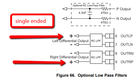
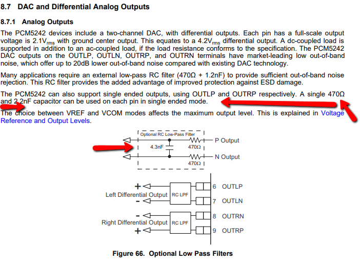
I have a new design. The design requires the option for both Single Ended and Differential to work at the same output pins. I plan on integrating the low-pass filter as described on page 44 Figure 66. I also appreciate the ESD protection it provides. 

Does the following filter allow for a single ended connection to be simply connected to the + pins of the left/right channels? Or does this filter require a differential connection at the output when used. It says in the datasheet "The PCM5242 can also support single ended outputs, using OUTLP and OUTRP respectively. A single 470Ω and 2.2nF capacitor can be used on each pin in single ended mode". This circuit is slightly different than that. But will it work as an "optional differential/single ended" output?


Is it possible to connect both single ended and differential devices to this exact same circuit? What about if this happens at the same time? Would that be a problem? Does this require a differential to single ended conversion? I hope not. This would be easier! :-)

Thanks for the help!

Jay

  • Hi Jay,

    Yes, you should be able to just use the L+/R+ as a single ended output. Though I would take care when routing the PCB. You should use a RC for each line, but consider that in SE mode the current return path is to the AGND pin of the PCM. So make sure that you have a clean path for AGND. In differential mode, the two pins are their own return paths. From a routing perspective you should have consider routing L+, L-, and AGND in parallel to ensure a good return path.

    Thanks!
    Paul
  • Hi Paul,

    Thanks for the response. On another post on this forum a user refers to the following optional filters. 

    But in the datasheet it says it wants 2.2nF when it's single ended. Or 4.3nF when it's differential. There are no "type a" or "type b".

    My design has pins for Gnd, +, - for all connections. So whether in single ended or differential, we should have a good ground. So the question is whether or not we can just simply leave the 4.3nF capacitor in place, connected to pin 2 (minus), and just simply tap the Plus and the Ground for that single ended output. Or do we still need to have a switch to ground out pin 3 (minus) and switch the capacitor to 2.3nF instead?

    Thanks!

    Jay

  • Hi Jay,

    I think the text is not really referring to your application, as the OUTxN would not be used. I think that your Type B figure is good for you application. In your PCB layout you can try to make the grounded side of both caps the same node with a good return path back to the AGND of the device. The value of the C is not as critical, as the PCM5242 has good out of band noise performance up to about 200kHz. If you fC is some between 24k and 200kHz I think you will have good filtering.

    Thanks!
    Paul