This thread has been locked.

If you have a related question, please click the "Ask a related question" button in the top right corner. The newly created question will be automatically linked to this question.

Help DSK6416 + ADS1174EVM communication

Other Parts Discussed in Thread: ADS1274, ADS1174, ADCPRO, DAC8554, TMS320C6416, ADS1247, ADS1147, DAC8554EVM

Hi, 

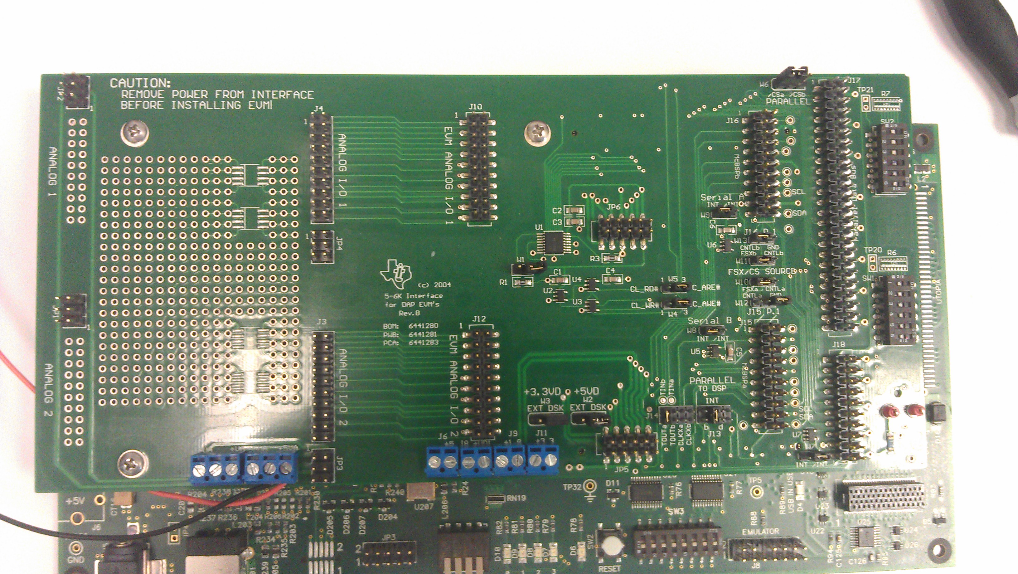
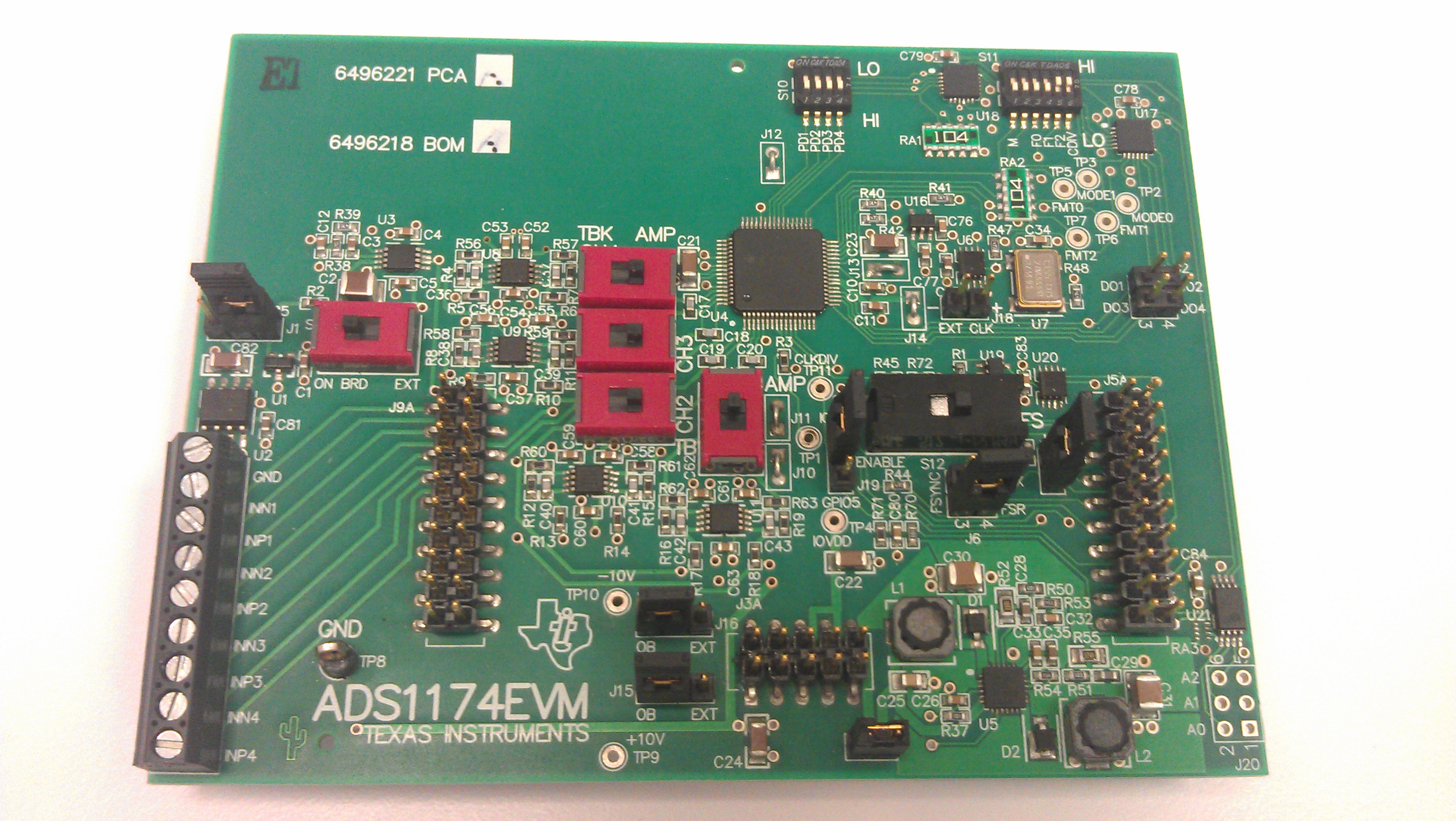
I want to use an ADS1174EVM to input some values to a DSK6416 board through a 5-6k interface board. Is there any information about how to do this from the scratch?. I got a project that uses the 6416 and the ADS1274 but after trying it, it does not work. So I am trying to understand how to program the Mcbsp port as master to use SPI with the ads. Is there any information also about how to setup the jumpers and switches of the different hardware (DSK. ADS, 56-K card).

Thanks in advance,

Ivan

  • Hi Ivan,

    The jumper settings for the hardware are in the main.c file that we talked about in your earlier posting.  The actual ADS1174EVM uses the same printed wiring board as the ADS1274, so the jumpers should all be the same.  The biggest difference between the two devices is the speed and the number of bits.  In the project archive there is a file called t1274_fn.h.  That file sets up the McBSP receive register for 24-bit transfers, so that is one thing that would need to change - the ADS1174 is only 16-bits.

    You mentioned also that the example code does not work, but can you expand a little on that?  Do you see any activity on the frame sync or any response from the ADS1174 at all? 

  • Hi Tom,

    I have configured everything as stated in the main.c of the project. I attach a couple of photos of the ADS1174evm module and the 5-6K interface card where you can see how the jumpers are set up. After, I changed the McBSP receive register (SPCR) and change RWDLEN1 to 16 bits. Done this, I compiled and run the code. I checked with the osciloscope all the signals. I can only see in J5.3   (CLKX) the clock wich runs at 22 Mhz more or less.

    I have checked all the pins of the adc (directly on the chip) and no signals arrive (no CLK, no FS and no even data). Well the FSYNC/DRDY is at 5V all the time.

    I have a ADS1174EVM-PDK. When connected and used with the MMB0 and the ADCPRO + the plugin, it works and it inputs values. I also checked the signals under this conditions and they arrive correctly to the ads. However, the setup of some jumpers changes (it works with the factory default setting).

    So basically, nothing arrives to the ADS1174. I think that the CLK should arrive even if the project is not running, shouldn´t it?. To start with it is a missconfiguration of the jumpers?. For example J18 only has two pins and in the main.c it says to close pins 1-2. From 2007, did the schematic change? (remember what happened with the DAC8554 that it had been down with a previous version of the board).

    What do you suggest? At this point I am quite lost.

    I attach the images of the boards with the pins so you can see that they are correctly settled.

    Here the description of the configuration as it is in the main.c of the project. 

    * Jumper settings for the 5-6K Interface Board (Rev B): */
    /* W1: open W5: 2-3 */
    /* W2: 2-3 W6: 1-2 */
    /* W3: 2-3 W7: 2-3 */
    /* W4: 2-3 W12: open */
    /* All others: don't care */
    /* J13: INTb J14: don't care */
    /* SW1: All closed */
    /* */
    /* Power connections on the 5-6K Interface Board: */
    /* J2: +5V */
    /* */
    /* Settings for the ADS1274 EVM Rev. A */
    /* J1: 1-2 (3125) J16: 1-2 (OB) */
    /* J4: Closed J17: Closed */
    /* J6: 3-4 (FSR-FSYNC) J18: 1-2 */
    /* J15: 1-2 (OB) J19: 1-2 (IOVDD) */
    /* */
    /* S1: ON BRD (left) */
    /* S2 - S9: AMP (right / up) */
    /* S10: All "OFF" (HI) */
    /* S11: 1-4 "OFF" (LO) */
    /* 5-6 "ON" (HI) */
    /* */
    /* Analog signal connections on the ADS1274 EVM: */
    /* Apply signal to J9A pin 1 and 2 */
    /* Analog signal settings: */
    /* - Frequency: 600Hz */
    /* - Amplitude: 4.5Vpp */
    /* - Offset: 0V */
    /* */
    /* All the H/W settings above translate to the following */
    /* settings in the data converter support tool: */
    /* DSP Tab: DSP-Type: TMS320C6416 */
    /* DSP Clock: 600 MHz */
    /* ADS1274 Tab: Serial Port: McBSP2 */
    /* Serial Port Format: FS, TDM, Fixed */
    /* Conversion Mode: High-Speed */
    /* Master Clock Frequency: 30000.000 */
    /* Power Down: All unchecked */

    Thanks 

  • Hi Tom,

    I found an html file (ADS1274-DSK6416.htm) inside the project folder. It says that the literature number is sbau129a.pdf. I have been looking for the doc but did not find it.

    Could I have access to the document?? Also, could you send me the board schematics of 2007?. I want to check if some of the pins names/routing have changed.

    Thanks,

    Ivan

  • Hi Ivan,

    The document is attached.  Here are some additional changes that would need to be made:

    • eDMA word length: change from 32 to 16 bit
    • McBSP word length: change from 24 to 16 bit
    • Pointer to buffer: change from long * to int *
    • Transfer object definition: change from long to int
    • Removal of modes not supported by the 1174 (high resolution and low speed are not supported)
    • Adding of the clock switch possibility for the high speed mode (not supported at the 1278)
    • Removal of the modulator mode
    • Changing of the calculation of the frame period from [4][2] to [2][2]

    7356.sbau129a.pdf

  • The schematics of the document correspond to the ADS1278EVM. Are they the same for the ADS1174EVM?. If don´t, could you send me the ones of the ADS1174?. I am going to check all the changes you told me and I´ll get back to you.

    Thanks a lot,

    Ivan

  • Hi Ivan,

    Yes, essentially the same schematics...attached is the previous version of the ADS1174 users guide.


    2772.sbau134b.pdf

  • Hi Tom,
    Here what I did till now so far:
    • eDMA word length: change from 32 to 16 bit. OK. (I changed element size to 16 bits from OPT register in t1274.h)
    • McBSP word length: change from 24 to 16 bit OK. (I changed RCR, XWDLEN1 to 16 bits). However did not touch XCR register.
    • Removal of the modulator mode. OK. I commented all the parts that were mentioning the modulator mode.
    • Changing of the calculation of the frame period from [4][2] to [2][2]. OK.
    • Removal of modes not supported by the 1174 (high resolution and low speed are not supported). OK. I left only the two modes of the ads.
    What is what I have to do for the other changes??
    • Adding of the clock switch possibility for the high speed mode (not supported at the 1278)
    • Pointer to buffer: change from long * to int *
    • Transfer object definition: change from long to int
    Thanks
  • Checking with the osciloscope I can see the CLK-SCLK at 27 Mhz. The data is arriving well but the the FSYNC is not present.

    I have connected the MMB0 board and checked again the signals. Everything but the FSYNC signal seems similar. For some reason the FSYNC is not arriving. Any ideas?.

    Ivan.

  • Checked directly on 5-6K interface board connector J15.1 and loaded the program and I can see the FSYNC signal on the 5-6K. However when I connect the ads1174evm it does not arrive to the J5 connector. Maybe it might be a missconfiguration of pins?. The setup as I have it is the one I sent you in the previous photos.

    Iván.

  • Hi Ivan,

    On the 5-6K Interface board, J15-1 would be related to the /SYNC input, not the Frame Sync.  The code example does not use the transmitter side of the McBSP - it only uses the recieve side.  When you run the code without using the ADS1174 board, you should be able to see the clock on J15 pin 5 and the Frame Sync on pin 9.  The shunt on J6 of the ADS1174EVM would need to be moved to cover pins 3-4.

  • Hi Tom,

    After several trials and compilation I am now able to input some values through the ads1174evm and store them in memory. However it seems to store some strange values. I input a sine of 1000 Hz  in INN1-INN2 and what I get is this.

    Between values of the input there are 3 samples that do not correspond to the signal. My question here is:

    Does the program sample from the 4 INN channels?. If yes, do these values corresponde to the input in the other channels (which is 0). I have tried to input signals in more than one channel and the results don´t look good.

    How can I select only one channel to input? or just change which channels to use?. The code uses the function dc_readblock.

    Another thing, the program works in EVM I/O 2 of the 5/6 card (J15,J12,JP5). I need to change this to make it work in the the I/O 1 (J16,J10,JP6) so I can plug the DAC8554 and make both work at the same time.

    How can I do this in the project code? I have checked the code but I did not find how to do it.

    Thanks,

  • The input of INN1 looks like this.

  • Hi Ivan,

    The capture above looks like you have some data interleaved, so it might be plotting data of IN1 with the other channels.  Left click on the graph and change the index to 4.  As for changing from I/O2 to I/O1, look in the DC_CONF.h file.  The serial port setting is defined there.

  • Hi Tom,

    Is there any possibility of sampling only directly from one channel (setup the number of channels I want to sample from)?

    Regards,

  • Hi Ivan,

    Take a look at page 17 of the data sheet to read a little about the formatting options of the data. If you use the hardware switches to power down the unused channels and configure the format pins for SPI, TDM, Dynamic mode, the ADC will just output data from the channel powered up and shift over the powered down channels.That should give you what you want where you convert directly from one channel, essentially turning the ADS1274 into a single channel converter.

    Regards,

    Tony Calabria

  • Hi Ivan,

    The code was written to get the data in TDM mode, so it would take a little doing to get just one channel of data.  The Format pins are controlled through the I2C expander's on the board and they are set via the SW.

  • Thanks Tony for your answer. I will have a look and get back to you with the results.

    Right now I am having problems to use the  I/O 1 of the 5-6 card to plug the ads. When the board is on I/O 2, the program works and I can see the values of the signal loaded into memory. However, when I change and plug the ads on I/O 1 the program gets stuck. I changed the port so I should work.

    The program loads the buffer one time but later it gets stuck in line 579 of t1274_ob.c and no more values are loaded:

    /* make sure the cache is coherent */
    CACHE_wbInvL1d((void *)pData,4 * uiCount, CACHE_WAIT);

    I presume it should be something related with memory management. I did not change anything so I guess it should work.

    What kind of problem could be this and how to fix it?.

    Thanks


  • Hi,

    After checking and setting everything up, I am now able to input values with the ADS1174 and output them with the DAC8554. I set up the receive and write interruptions of the McSBP ports and create a couple of functions that read the values and output them. The code is like this:

    void getMCSBPData(void){  /*function to execute when reading interrupt McBSP port 0*/

    data=MCBSP_read(hMcbspADS1274);

    }

    void writeMCSBPData(void){  /*function to execute when writing interrupt McBSP port 2*/

    MCBSP_write(hMcbspDAC8554,data); 

    }

    This is the basic code I am using now (some control flags for synchronization are used but the should not interfere).

    I would like to be able to do this operation in Real Time. Right now, I have a minimum delay between the input and the output of 1.5 ms.

     If the ADS samples at 50000 samples/s (I tested it) and with 4 channels, i should be able to get a delay of just 1/12500 s (considering that it samples the 4 channels and there is only one sample delay).

    Is there a way to improve this and make it shorter (closer to Real Time)?.

    Thanks,

    Ivan

  • Hi Ivan!

    I am happy to hear that you've made some (significant) progress!  I don't have anyone on staff at the moment that will be able to help optimize your code to get nearer to 'real time' transfer.  You might consider posting a query to the C6000 support forum.  They are much more familiar with the code caveats than we are and I suspect they could help you resolve this faster than my team could.

  • Thanks a lot for your help, it has been extremely valuable. I will post the issue in the C6000 forum.

    Best,

  • Tom,

    Sorry to disturb again. As I told you the ADC works based on the code generated by the Data Converter Plugin for the 1274 ADC. I haven´t changed anything in the configuration of the McBSP and the values I get for the input are scaled to 24 bits (as the 1274 works in 24 bits). As the 1174 is a 16 bits device, I would like to received the values between +32767 and -32768 and not in the range of 24 bits.

    I have changed the RWLEN1 of the SPCR register of the MCBSP to 16 bits (t1274_fn.h). The thing is that now I get only 0s. I changed it to 32 bits and it seems to scale work and get the values in the range of 32 bits.

    Is there any other parameter that I should change in order to receive the values scaled in 16 bits?.

    Regards,

    Ivan

  • Hi again Ivan,

    Now that I have your attention!  (Sorry about that last post, I was thinking of someone elses problem...)

    So, the ADS1147 should work with the ADS1247 code, you just need to right shift by 8-bits to get the data in the +32767 to -32768 range.

  • Hi Tom,
    I got a new board with the ADS1274 EVM PDK on it so the problem with the 16 bits transmision is solved. It seems to work quite well. I am even now able to change modes and sample from one channel only.
    Looking at the datasheet of the ADS1274 converter it says that the input voltage is from -Vref to +Vref (page 3) if I am not mistaken. Having the reference onboard which is 2.5 V, when I input a signal of smaller than 0 v, the conversion is clipped. Looking at Page 24 there is a description of the inputs and it mentions the bipolar operation:
    The ADS1274/78 measures each differential input signal VIN = (AINP – AINN) against the common VREF = (VREFP – VREFN). The most positive measurable differential input is +VREF, which produces the most positive digital output code of 7FFFFFh. Likewise, the most negative measurable differential input is –VREF, which produces the most negative digital output code of 800000h.
    For optimum performance, the inputs of the ADS1274/78 are intended to be driven differentially.
    For single-ended applications, one of the inputs (AINP or AINN) can be driven while the other input is fixed (typically to AGND or +2.5V). Fixing the input to 2.5V permits bipolar operation, thereby allowing full use of the entire converter range.
    While the ADS1274/78 measures the differential input signal, the absolute input voltage is also important. This value is the voltage on either input (AINP or AINN) with respect to AGND. The range for this  voltage is:
     –0.1V  - (AINN or AINP) +  AVDD + 0.1VIf either input is taken below –0.4V or above (AVDD + 0.4V), ESD protection diodes on the inputs may turn on. If these conditions are possible, external Schottky clamp diodes or series resistors may be required to limit the input current to safe values.
    What do I have to do to be able to use an input range -2.5 to 2.5v ?. 
    Regarding the DAC8554EVM user guide (sbau121.pdf) it also makes reference in Page 16 to bipolar operation mode. Does this mean that the device circuit is able to output also negative values?.
    Regards,
  • Hi Ivan,

    The ADS1274 cannot accept negative inputs - you'll have to maintain your signal in the 0-5V range.  The differential input to the ADS1274 is +/-Vref, but that is at a common mode level of +2.5V.  The DAC8554EVM can be configured to output 0-5V or +/-2.5V.  If you are feeding the output of the DAC into the ADS1274, configure it for unipolar output and then apply the 0-5V to the (+) terminal of the ADS1274, you can then put a fixed +2.5V on the (-) input.

  • Hi Tom,

    Regarding the ADS1274EVM, it works with bipolar signals withing a range of -2.5 to +2.5 v. The problem comes when I connect the DAC8554EVM and I power it with the -15 +15v. I dont know why but it keeps clipping the signal read by the ADC1274 and only works from 0.5 to 2.5. This happens when I connect the -15 +15 supply of the DAC8554.

    Do you have any idea of what is going on?.

    To power the whole system I use two laboratory power supplies to generate the 1.8, 5 and +15 -15 V. Could it be a problem with the GND??.

    I havent been able to make the DAC EVM module work in bipolar mode although I have followed he instructions. I cant see the signal in J4.5 of the operational that I presume should be bipolar.

    Thanks,

    Ivan

  • Unfortunately no, I don't.  Let me try to hook up these two EVMs here on Monday and we'll see what happens...

  • Hi Tom,

    Well I found out that the problem with the ADCs (both ads1174 and ads1274) only occurs when I buffer the input through S2,S3,S4,S5 for the ads1174 and S4,S5,S7,S8.

    I do not like a lot this option because in case of any problem, the buffering circuit might protect the converter from getting burned but the circuit works well.

    So from my point of view, something is being done by the buffering that clips the signal when I input bipolar.

    What could it be?

    The other thing the bipolar mode of the DAC8554. I set everything up as described in the pdf of the 8554evm (section 3.4. Unity gain output). I put JMP10 in position 1-2 but the output is unipolar (0-5 V).

    What should I do to get it bipolar?.

    I have two DAC8554evm modules and one has the OPA627AU Output Op Amp burnt. Is it possible to get a free sample of it?. If not, one that could work and I could get  a free sample?.

    Thanks,