This thread has been locked.

If you have a related question, please click the "Ask a related question" button in the top right corner. The newly created question will be automatically linked to this question.

LMP90078 conversion after "Power-Down"

Other Parts Discussed in Thread: LMP90078, LMP90100

I would like to measure an RTD every period of time (from 1 min to 1 hour) and set the LMP90078 to “Power-Down” mode between measurements.

I’ve got the device to measure in “Single channel, Continues scan” but every time I’m setting in to “Active mode” it will wake up but after reading the conversion it fails on CRC check.

My goal is to get the following sequence every minute:

Set to Active mode

Read sample

Set to Power-Down

I’ve attached my register settings. And my circuit is as described in the datasheet figure 65.

 TI_LMP90100_register_settings.h

  • Hi Yuval,

    Are you getting good ADC results when you switch from Power-down mode to Active mode? The CRC is only done on the ADC data (ADC_DOUTH and ADC_DOUTL).  It does not apply to the other registers.

    Can you please provide the schematic of your design and SPI scope shots or logic analyzer captures of the issue? 

    Regards,

    Mo.

  • Hello,

    Please try the following:

    Set to Active mode

    Read sample, discard

    Read sample and CRC register

    Set to power down.

    Does that give better results?

    Also, just to make sure, when using the single channel continuous scan mode gain needs to be < 16 and you cannot use BgcalMode1 or 2.

    Mike

  • Hi Mike,

    I've try the sequence with no luck. The is will not pass CRC check. Here is my schematics:

    Here is my code:

      addr = TI_LMP90100_SENDIAG_FLAGS_REG;                                    // Start Reading from ADC_DOUT2 Register
      count = CH_DATA_SIZE;                                                    // bytes to read: ADC_DOUT2 - ADCDOUT0, CRC
      TI_LMP90100_SetActive(&prev_URA);
      TI_LMP90100_SPINormalStreamReadADC(TI_LMP90100_ADC_DOUT2_REG, read_buf, 2, &prev_URA);    // read adc output into read_buf
      TI_LMP90100_SPINormalStreamReadADC(addr, read_buf, count, &prev_URA);    // read adc output into read_buf
      TI_LMP90100_SetPowerDown(&prev_URA);
      ch_status = read_buf[0];                                                 // Get Channel Status byte
      crc_test = TI_LMP90100_SPICRCCheck(read_buf, CH_DATA_SIZE-1);
      if ((crc_test == CRC_PASS) && (ch_status == 0))
      {
    	 adc_data = ((uint16_t) read_buf[1] << 8) | read_buf[2];                  // form raw adc output data
    	 res = ((float)adc_data) * 4000.0 / 65536.0 - 1000.0;
    //	 temp = linear_interp(0,200,res);
    	  /* Show Celsius on numeric part of display */
    //	  i = (int)(temp * 100);
    	  i = (int)(res*1000);
    	  SegmentLCD_Number(i);
    //	  SegmentLCD_Symbol(LCD_SYMBOL_DP10, 1);
    //	  SegmentLCD_Symbol(LCD_SYMBOL_DEGC, 1);
    //	  SegmentLCD_Symbol(LCD_SYMBOL_DEGF, 0);
      }
      else
    	 adc_data = 0;
    

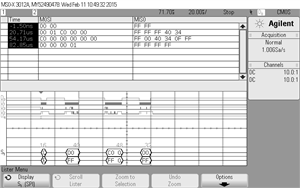
    and here is how it looks on the scope:


    When I comment out the SetPowerDown function, the CRC and the readings are fine.

      addr = TI_LMP90100_SENDIAG_FLAGS_REG;                                    // Start Reading from ADC_DOUT2 Register
      count = CH_DATA_SIZE;                                                    // bytes to read: ADC_DOUT2 - ADCDOUT0, CRC
      TI_LMP90100_SetActive(&prev_URA);
      TI_LMP90100_SPINormalStreamReadADC(TI_LMP90100_ADC_DOUT2_REG, read_buf, 2, &prev_URA);    // read adc output into read_buf
      TI_LMP90100_SPINormalStreamReadADC(addr, read_buf, count, &prev_URA);    // read adc output into read_buf
    //  TI_LMP90100_SetPowerDown(&prev_URA);
      ch_status = read_buf[0];                                                 // Get Channel Status byte
      crc_test = TI_LMP90100_SPICRCCheck(read_buf, CH_DATA_SIZE-1);
      if ((crc_test == CRC_PASS) && (ch_status == 0))
      {
    	 adc_data = ((uint16_t) read_buf[1] << 8) | read_buf[2];                  // form raw adc output data
    	 res = ((float)adc_data) * 4000.0 / 65536.0 - 1000.0;
    //	 temp = linear_interp(0,200,res);
    	  /* Show Celsius on numeric part of display */
    //	  i = (int)(temp * 100);
    	  i = (int)(res*1000);
    	  SegmentLCD_Number(i);
    //	  SegmentLCD_Symbol(LCD_SYMBOL_DP10, 1);
    //	  SegmentLCD_Symbol(LCD_SYMBOL_DEGC, 1);
    //	  SegmentLCD_Symbol(LCD_SYMBOL_DEGF, 0);
      }
      else
    	 adc_data = 0;
    

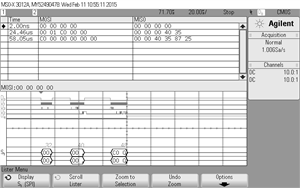
    and here is how it looks on the scope:

     waiting for you suggestion.

    Thanks,

    Yuval

  • Hi Mo,

    I think the is no conversion after my power up, do I need to sent "conversion reset" and wait?
    See my reply to Mike for schematics and scope capture.

    Yuval
  • Hi TI,

    Another issue I need help with is. that reading are changing with the amount of current I'm driving. With the circuit above, I'm changing ADC_AUXCH from 100uA to 500uA

    and I read different values. I thought that since I'm using both current sources they cancel each other in the calculations and should have no effect on the measurements.

    Yuval

  • Hi Mike, 

    Please correct me if I am wrong.

    Yuval: 

    With 100uA excitation current you are violating the min Vref specs of the LMP90078 as specified in the datasheet at page 8:

    With IB1=IB2=100uA  and Rref = 1k ohm in your configuration:

    Vref = 2 x IB1 x Rref

    Vref = 2 x 100uA x 1k ohm =  0.2V

    So IB1= 100uA with Rref = 1k ohm can't be used in this case. Basically the value of Rref is selected based on the IB setting and the desired VREF voltage.

    To clarify, can you please provide the below information:

    1) What is your desired differential input signal range (according to the full scale temp range in your application using the PT-100)? 

    2) What is your gain setting? The maximum allowable PGA gain setting is based on the reference voltage, the RTD resistance change, and the excitation current (please see chapter 3.1.3 of TIPD120)

    3) Also, it seems that you have a mismatch in your input and Reference Low-Pass Filters. C29 must be 10 times bigger than C28 as well as C32 which must be 10 times bigger than C31. In your configuration these are swapped! Please see chapter 3.2.2 of TIPD120  and also here)

    These app notes are based on the ADS127x family devices but can be also be used for the LMP90xxx family devices.

    Regards,

    Mo.

  • Mo. said:

    1) What is your desired differential input signal range (according to the full scale temp range in your application using the PT-100)? 

    I measuring a PT1000 from   603ohm to 1565ohm, with 700uA IB it translate to 0.4221-1.0955 Volts, with 1K Rref, and 3V supply.

    Mo. said:

    2) What is your gain setting? The maximum allowable PGA gain setting is based on the reference voltage, the RTD resistance change, and the excitation current (please see chapter 3.1.3 of TIPD120)

    Right now my entire gain is 1.(see registers value in the file attached in the beginning of the thread.

    Mo. said:

    3) Also, it seems that you have a mismatch in your input and Reference Low-Pass Filters. C29 must be 10 times bigger than C28 as well as C32 which must be 10 times bigger than C31. In your configuration these are swapped! Please see chapter 3.2.2 of TIPD120  and also here)

    You are right, I did get it backwards.

  • Yuval Klein said:
    I measuring a PT1000 from   603ohm to 1565ohm, with 700uA IB it translate to 0.4221-1.0955 Volts, with 1K Rref, and 3V supply.

    The 700uA excitation currents with Rref = 1k will produce a 1.4V reference. With gain of 1 your Vin_min (0.4221V) and Vin_max (1.0955V) are well within the analog common-mode input voltage range of the LMP90078.

    However, if high precision is needed in your application then you may want to take a 820ohm precision Rref resistor (0.02% maximum tolerance) instead of the 1k ohm resistor which will produce a 1.148V reference. I.e. you can have a look at the Susumu RG2012V-821-P-T1.

    Regards,

    Mo.

  • Hi Mo,

    I understand and I will change the resistor to 820ohm. I did follow the design reference and since I'm using 2 matching current sources and ADC DATA should be the same for different currents (1000-500uA) but I'm getting different readings for each setting. why?

    The more important question is how to wake up the LMP90078 from power down--> take a sample--> and putting it back into power down, right now it will not go though a conversion after setting it to active mode.

    Yuval

  • Yuval,

    Yuval Klein said:
    I did follow the design reference and since I'm using 2 matching current sources and ADC DATA should be the same for different currents (1000-500uA) but I'm getting different readings for each setting. why?

    Without having your full schematic and layout it is difficult to debug the issue you are observing. I highly suspect that this might be due to the mismatched RC filters at the input path and also at the reference path resulting to dc offset errors. How did you design the -3db corner frequencies of the RC filters? 100k ohm for R3 and R7 seem way to much. They should be below 20k! What is your Sampling rate?

    - Can you provide reading results when using 1000uA and 500uA currents when using both the RC filters at the input and also at the Reference?

    - Then we need the reading results of the RTD measurement under the same conditions but this time with the RC filters removed!

    Yuval Klein said:
    The more important question is how to wake up the LMP90078 from power down--> take a sample--> and putting it back into power down, right now it will not go though a conversion after setting it to active mode.

    Unfortunately I don't have the evaluation board to replicate your issue but I can ask my colleague to look at this.

    Kind Regards,

    Mo.

  • Hi, Mo

    I reviewed my filter design and it according to your recommendations and it fixed the problem.

    As you see I'm using PT-1K and not PT-100, my sampling rate is 13.42SPS and I've choose 150Hz as my -3dB cutting frequency.

    My Rrtd is 1K. I will later change Rref to 820 and redo the filter.

    By the way the circuit is, right now, on solderless protoboard (no layout).

    The only remaining issue is how to sample after power down.

    Regards,

    Yuval 

  • Hi Yuval,

    Glad to hear that you have managed to solve the problem with the input/reference filter. Make sure you follow the layout recommendations as shown in the datasheet and the EVM User's guide.

    As for the power-down issue, I have asked my colleagues to look into it. We will get back to you as soon as possible.

    Regards,
    Mo.
  • Hi Yuval,

    This is the information I received from the Apps team:

    "The Device needs to be in continuous conversion mode to convert. Or single shot mode for it to automatically convert on active mode."

    Regards,
    Mo.
  • Hi Mo,

    Mo. said:


    "The Device needs to be in continuous conversion mode to convert. Or single shot mode for it to automatically convert on active mode."

    I already know that. I've try setting the device to "single shot" and periodically doing the following sequence:

      addr = TI_LMP90100_SENDIAG_FLAGS_REG;                // Start Reading from ADC_DOUT2 Register
      count = CH_DATA_SIZE;                                                    // bytes to read: ADC_DOUT2 - ADCDOUT0, CRC
      TI_LMP90100_SetActive(&prev_URA);
      TI_LMP90100_SPINormalStreamReadADC(TI_LMP90100_ADC_DOUT2_REG, read_buf, 2, &prev_URA);    // dump the first conversion
      TI_LMP90100_SPINormalStreamReadADC(addr, read_buf, count, &prev_URA);    // read adc output into read_buf
      TI_LMP90100_SetPowerDown(&prev_URA);
      ch_status = read_buf[0];                                                 // Get Channel Status byte
      crc_test = TI_LMP90100_SPICRCCheck(read_buf, CH_DATA_SIZE-1);
      if ((crc_test == CRC_PASS) && (ch_status == 0))
      {}

    The problem is that it will convert only once and every time after that I'll get crc error.

    Please forward it to them and ask them for a code right sequence to sample periodically using "single shot" and power down between samples.

    Thanks,

    Yuval