This thread has been locked.

If you have a related question, please click the "Ask a related question" button in the top right corner. The newly created question will be automatically linked to this question.

Suggestions digital 4-20mA

Genius 3300 points
Other Parts Discussed in Thread: XTR116, DAC8750, DAC8760, DAC7750, DAC161P997, DAC161S997

1. Hi I am looking for digitally controlled 4-20mA current output.
Max voltage will be 24V dc , 16 bit , SPI based preferable.

2. I have looked for xtr116 , but it has analog voltage control.
DAC8750 seems to be Ok as it 16 bit & spi based.
DAC8760 had added feature of voltage out so for me its not reuired

So I would probably go for DAC8750


3. Any other ic or suggestions?

  • Vindhyachal,

    If you are designing a 3-wire transmitter, then the DAC8750 is probably your best choice. As you probably noticed, there are also other members in the family that are 12-bit products. The DAC7750 is the 12-bit version of the DAC8750.

    If you are designing a 2-wire transmitter, DAC161S997 is your best choice. There is also a sibling device here with a different interface called the DAC161P997.
  • Kevin,

    Thanks for reply.

    I have selected DAC8750 for the application. I have control current 4-20mA based on data sent over SPI

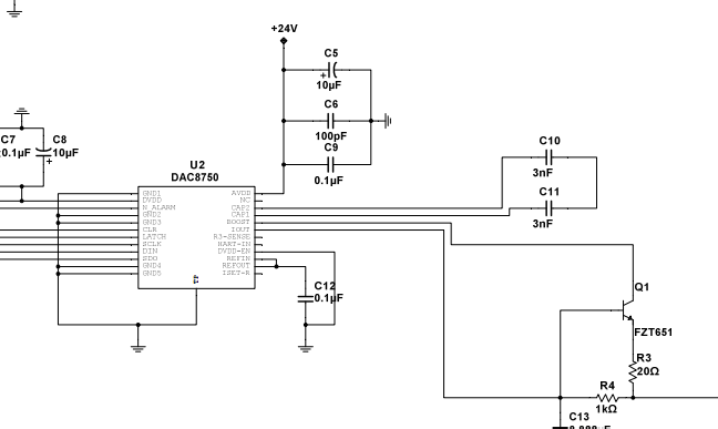
    1. I have attached the circuit.

    2. I have left R3-sense open. Is it right? 

    3. Similarly I have left open Hart-In & Iset-R open, since i am not using hart protocol. is it right?

    4. I will not slew rate feature. So is it ok to left open cap1 & cap2 pin,  or some capacitor value is recommended. If yes, what should be default value?

    5. Any other comment on circuit.

    6562.ckt.pdf

  • Vindhyachal,

    Vindhyachal Takniki said:

    2. I have left R3-sense open. Is it right? 

    3. Similarly I have left open Hart-In & Iset-R open, since i am not using hart protocol. is it right?

    This is fine. If you'd like to avoid leaving some of these nodes floating, you can AC couple HART-IN and R3-SENSE to GND but this is not required.

    Vindhyachal Takniki said:
    4. I will not slew rate feature. So is it ok to left open cap1 & cap2 pin,  or some capacitor value is recommended. If yes, what should be default value?

    It is okay to leave these nodes floating. When these capacitors are in use, though, they should be in series between the CAP1 or CAP2 pin and AVDD. Right now your schematic has CAP1 in series with two capacitors back to CAP2.

  • Hi Kevin,

    I have attached the updated circuit.

    1. I have decoupled R3-sense & Hart-in pin with 0.022uF as shown. Is it correct?

    2. "When these capacitors are in use, though, they should be in series between the CAP1 or CAP2 pin and AVDD. Right now your schematic has CAP1 in series with two capacitors back to CAP2"

    I didn't get what u are saying here. Can you show some example.

    I have taken the reference from circuit in SBAU205A (page 21) , it has capacitor connections on CAP1 & CAP2 pin as I have done.

    Edit: 3. Is it ok to leave ISET-R pin floating?

    5460.ckt.pdf

  • Vindhyachal Takniki said:
    1. I have decoupled R3-sense & Hart-in pin with 0.022uF as shown. Is it correct?

    Sorry - I miss-spoke (or miss-typed, as it were) what I meant to say here. I meant to suggest AC coupling HART-IN and ISET-R, not R3-SENSE. It's still okay to short R3-SENSE but it's not really as relevant as it would be to do it to the other pins, I would suggest you just leave R3-SENSE floating.

    Vindhyachal Takniki said:

    2. "When these capacitors are in use, though, they should be in series between the CAP1 or CAP2 pin and AVDD. Right now your schematic has CAP1 in series with two capacitors back to CAP2"

    I didn't get what u are saying here. Can you show some example.

    I have taken the reference from circuit in SBAU205A (page 21) , it has capacitor connections on CAP1 & CAP2 pin as I have done.

    The new schematic is correct.

    Vindhyachal Takniki said:
    Edit: 3. Is it ok to leave ISET-R pin floating?

    As I mentioned above, you could AC couple this pin to GND if you'd like or leave it floating.

  • Hi Kevin,

    Thanks for reply.One confusion remains, otherwise its ok.

    In Post#4 you have said that

    "It is okay to leave these nodes floating. When these capacitors are in use, though, they should be in series between the CAP1 or CAP2 pin and AVDD. Right now your schematic has CAP1 in series with two capacitors back to CAP2."

    while in post#6 you said

    "The new schematic is correct."

    However I didn't made any changes in cap1 & cap2 capacitors connections.

    For clarity sake, I have attached same schematic with below changes:

    1. Iset-R & Hart-in are decoupled by 0.022uF cap each.

    2. R3-sense is left floating.

    3. A 3nF capacitor to each Cap1 & cap2 pin with second connection to ADVDD.

    Design1.pdf

  • Vindhyachal,

    I'm not sure what happened with your original schematic, maybe the PDF was corrupt. Here is what I saw:

    In any case, what you have now looks good.

  • Hi Vindhyachal,

    I facing some problem with DAC8750 handling. Please could you help me.

    i am able to write the DAC control register and read it properly but when i write DAC data its (current value) not changing at all on IOUT pin.

    I have gone through the DAC8760 example code. i have a doubt on LATCH pin.

    1 Do we need to make it high on DAC init routine? And make low before sending and make high after completion 

    2 Do we make it low on DAC init and make high to low after sending the data.

    i am using 2nd option as mentioned in example of DAC8760 code. Please suggest whether option 1 or 2. Or any other settings i am missing while DAC init routine( doing init as mentioned in DAC8760 example).

    Urgent help is need

    Nitesh 

  • Hi Nitesh,

    Nitesh Padiyar52 said:
    i am using 2nd option as mentioned in example of DAC8760 code. Please suggest whether option 1 or 2. Or any other settings i am missing while DAC init routine( doing init as mentioned in DAC8760 example).

    They are both valid as long as there is a rising edge on LATCH after the frame.

    Nitesh Padiyar52 said:
    i am able to write the DAC control register and read it properly but when i write DAC data its (current value) not changing at all on IOUT pin.

    What are you including in the DAC init routine?

    To get an output you at need to at a minimum:

    1. Enable the reference.
    2. Set the current mode.
    3. Enable the output.
    4. Write and update the data register.