This thread has been locked.

If you have a related question, please click the "Ask a related question" button in the top right corner. The newly created question will be automatically linked to this question.

ADS1018 DOUT/DRDY doesnt go low after nCS LOW

Other Parts Discussed in Thread: ADS1018

HI All ,

I Am working with ADS1018 and i having some issue , below is my configuration settings 

ADS1018 VDD = 4.096V (Reference Voltage)

Analog Input #0 =3.5V (Constant Voltage)

Analog Input #2-#4 =0V

Configuration = 0x426b

------------------------------

Single ended mode

Continuous conversion

 PGA=1

DOUT/DRDY pull up Enabled

NOP=Valid data, update the Config register

MUX[2:0]= AINP is AIN0 and AINN is GND

my transmission cycle is based on (32bit Data), during this cycle i am sending my configuration twice.

I have manged to read correctly  reading (with the configuration read back as expected) , when i start transmission cycle i am lowering

my nCS to '0' , and check  DOUT/DRDY  if '0' meaning new reading is available and continue with transmission cycle,

 else ( '1') new Reading is not available , in this case i don't continue with the transmission cycle and return nCS to '1' .

my problem is that sometimes the ADS1018 is 'Stuck' (DOUT/DRDY is '1' when i am lowering nCS to '0')  no matter how much time i am waiting between 

each iteration (each time is ~100ms) , can anyone please  advise ? 


  • Eyal,

    Thank you for your inquiry.

    Is this an intermittent issue on one device or have you observed this behavior on several devices? If you try it on multiple devices and see the same behavior, it might be a set up issue.

    Also, I am not able to understand Configuration = 0x426b, can you provide the 16-bit config register value, example 0x058Bh?

    Is it possible for you to scope the SPI interface pins? That way, we do not rely on software logic to look for DRDY pin transitioning low and also we make sure that our SPI signal waveform match-up with the 32-bit transmission cycle waveform shown in the datasheet.

    You might want to also check if we are not violating any SPI timing requirements in datasheet.

    Thanks,
    Krunal
  • HI Krunal ,

    Thank you for the quick response , i have seen this kind of behavior on two different units , but as i mention it happen sometimes.

    the Configuration word that i am sending is  0x4262h , i am sending it twice (during 32 bit transmission):

    MUX[2:0]  = AINP is AIN0 and AINN is GND

    PGA[2:0]=  FS is ±4.096 V

    MODE= Continuous conversion mode

    DR[2:0] = 920 SPS

    TS_MODE = ADC mode

    PULL_UP_EN = Pull-up resistor disabled on DOUT/DRDY pin

    NOP[1:0]: = Valid data, update the Config register (default)

    bit 0  = 0


    the ADC work as expected ,the converted voltage is what i measured using DVM , the Read back word is the same configuration Word that i have sent.

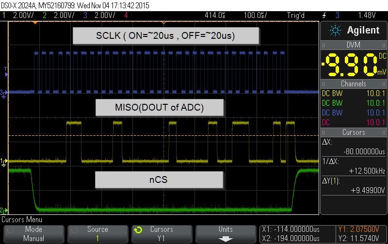
    below is snapshot of the SPI interface 


    but still i often encounter that the ADC is Stuck (e.g. nCS goes low while MISO is HIGH) , even if try to query several times  the MISO(DOUT of ADC) Stay High

    while the nCS is low , the interval between queries is ~ 100ms , Any idea ?

    Thanks ,

    Eyal 


  • Eyal,

    Thank you for your follow up.

    I am suspecting that the part is getting reset somehow and is out of continuous conversion mode when the issue happens. The default state of the part is single-shot mode. Can you only read the Config Register when this issue happens? You could keep the DIN low for the first 16-bits of the 32-bit transmission cycle to avoid writing to the Config Register and the next 16-bits should give you the Config Register readback value. If you do so, do you still readback 0x4262h?


    Thanks,

    Krunal

  • Hi Krunal ,

    I did some testing , and i'm suspecting it's not reset problem . i read the configuration word when this issue happen and  and the value i got is 0x7263.

    this match to what i have sent in the previous transmission cycle.

    To give a better picture of how i am reading , i will explain shorty the software logic , my purpose is to get reading from channels AIN0-AIN3 (single ended) and also the temperature.

    each time (~100ms) i am interfacing the ADC , i am  reading the current value(of the current channel)  and configure the ADC to sample the next channel (AINO-AIN3 or Temperture) , all in single 32bit transmission cycle.

    i hope this information may be clear up of what causing this issue .

  • Eyal,


    Can you try to extend out your time from when /CS goes low to when you clock out your first SCLK? You may also need to extend the time from the last SCLK to when /CS returns high again. It looks like your SCLK takes to long to transition going on and off and vice versa.


    Joseph Wu
  • Eyal,


    Sorry, I meant /CS is taking too long.


    Joseph Wu
  • HI Joseph ,

    Thank you for the advice , I had capacitor connected between the nCS pin to the GND , the rise time and the fall time of the nCS has  improved.

    i also added delay between nCS transition to LOW  and the first SCLK , and from the last SCLK to nCS transition to HIGH . i  also cheeked that 

    i respect all the timing requirement as instruct in the data sheet.

    But after all of these changes  , i still encounter the issue  .

  • Eyal,

    I just had few things in mind to try. You might have already tried it.

    1. Can you probe all the pins DIN/SCLK/DOUT/CS when you see the issue? I see that the scope shot that you sent previously was with a good case. Is there anything different that you are doing when you see the issue and when you don't see the issue? Does any event such as doing a supply reset and then starting fresh clean up the issue? Is their any test case or sequence, during which, you will never see an issue?

    2. Could you try a week pull-down such as a 100 kOhms to GND on DOUT/DRDY pin? I am wondering if it makes any difference.

    3. Are there any chances that your output level shifters (if you are using) are not set up correctly? I have seen that sometimes the level shifters direction or voltages are in a condition which could cause this kind of problem.

    4. Can you share the hardware schematic with us?

    Regards,

    Krunal

  • Hi Krunal ,

    I think i understand the scenario that causing this issue , i have succeed to view it on scope (unfortunately i don't have screenshot) .

    when this issue happens , after nCS goes to low the DOUT of ADC (MISO) is also low , but after ~20us it goes high for ~30us and than returns to low again.

    to solve this issue i add logic that check the DOUT after nCS goes LOW , and if DOUT is HIGH wait for ~30us , only then i preformed transmission cycle.

    what do think about this phenomenal ? is it normal behavior of the ADC ? 

  • Hello Eyal,


    This is not something we expect. Is it possible for you to send us the scope plot? If at all DOUT/DRDY goes high in continuous conversion mode, it should be high for 8us and not 30us. Are you changing the PULL_UP_EN bit in the configuration register in the previous transmission cycle? Can you try both the options, pull-up enabled and pull-up disabled, and see how your timing diagram is affected?


    Thanks,

    Krunal