This thread has been locked.

If you have a related question, please click the "Ask a related question" button in the top right corner. The newly created question will be automatically linked to this question.

Trouble setting up ADS1148

Other Parts Discussed in Thread: ADS1148EVM-PDK, ADCPRO, ADS1148, ADS1248

Hello,

I'm using the ADS1148EVM-PDK to measure a P100 RTD in 2 wire mode. The RTD is connected to AIN0 and AIN1.

For the board, I have removed R14 and R15. And replaced C20 with a 845Ohm resistor. This is my Rbias. I replaced C24 and C25 with 0 Ohm resistors. I removed C7. I attached a small wire from AVSS to one side of the 845 Ohm resistor and a wire from AIN0 to the other side of the 845Ohm resistor. 

From the ADCPro software, Power & Ref, I enabled Internal Reference. IDAC Magnitude is set to 500uA. And IDAC0 is set to AIN. From IO Config AIN1 has IDAC0 and AINP enabled. AIN0  is connected to AINN.

In my simulation, current is generated at idac0. Current flows through the RTD (AIN1 to AIN0) and the bias resistor (REF1P and REF1N). With 500uA, there should be a voltage drop of ~422mV across Vbias. Using a 110Ohm resistor, there should be a voltage drop of ~50mV across AIN0 and AIN1. This checks out with a multimeter (418mV & 54mV). 

Instead, VREF1 shows -0.00125V and 0.24382V across AIN0 and AIN1. I have tried unloading and reloading the EVM and Test multiple times as well as restarting ADCPro. I don't think it's a software issue. Any ideas as to why I am not seeing what I expect across VREF1 and AIN0/AIN1?

  • Diego,


    I've read through your modifications. I understand most of them, but replacing C24 and C25 with 0 Ohm resistors looks just shorts the inputs together to the ground. It would be better if these common-mode input filtering capacitors were just open.

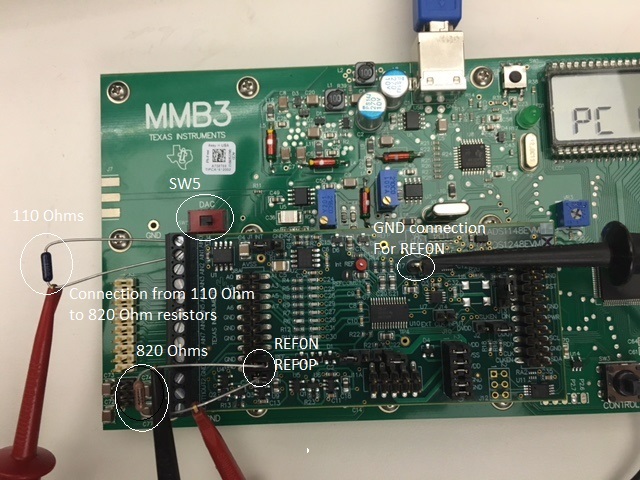
    Coincidentally, I set up an ADS1148EVM-PDK to measure a 3-wire RTD last week. However, I didn't modify the board to do this but used resistors similar to what you tried. I used a reference resistor of 820 Ohms and measured several resistors from 20 Ohms to 400 Ohms. With the 3-wire setup, I use 2 IDACs set to 1 mA each.

    I setup AIN0 as one IDAC output and AIN3 as the other IDAC output for lead-wire compensation. AIN1 and AIN2 are used for the RTD measurement. I set up REF0 as the reference input (which has connections on J8). I also set turned on the internal the reference, to enable the IDAC sources (but still use REF0 as the reference input).

    I did a set of measurements with PGA=4 and DR=20SPS and had no problems.

    With what you've described, I think the problem is with the C24 and C25 modifications you've made. It could also be a problem with the current routing setup for the IDACs. Make some measurements to make sure that your EVM is set up correctly with those and let me know if it helps.


    Joseph Wu
  • Diego,


    One thing that I want to point out is that you should be careful routing the IDACs to inputs that are also used for measurement. There will be voltage drop across the series filter resistors that should be accounted for. In the example I mentioned, that's why I use AIN0 and AIN3 for the excitation and AIN1 and AIN2 for the measurement.

    In that example the series resistance in front of AIN0 and AIN3 are not part of the input measurement, and the series resistance for AIN1 and AIN2 only see a small input current (less than 10nA or smaller depending on the data rate) across their series resistance.


    Joseph Wu
  • Hello Joseph,

    Thanks for the tips. First, C24 and C25 were removed not shorted. It's strange, if I use a multimeter I get the correct values. For example, I've replaced the RTD with a 110 Ohm resistor. Idac is set to 1mA. Using a multimeter, I get 110mV across the RTD and 845mV across the bias resistor. The bias resistor is 845 Ohm, so those values are correct.

    But when I use the EVM software, I see -0.244V across the RTD and -0.00088V across the bias resistor. I have a feeling I'm not using the EVM software correctly.
  • Diego,


    I'm not sure where the EVM is going wrong. Part of the problem might be that you've made some modifications to the EVM, and there was a mistake in the modification. Second, I'm not sure I understand how your setup is done. In the first paragraph of tje last post you say that the IDAC is set to 1mA and the multimeter readings are correct, but in the second paragraph, you say that you use the EVM software and the measurements are wrong. How did you set up the IDAC when the first measurements were correct? Normally this would be setup with the ADCPro software and if this is done correctly, what did you do setup in the software afterwards?

    Regardless, let's try to take this one step at a time. Lets look at the board itself first. Can you post a close-up photo of the board in its current state? I'd like to see what changes you've made and what resistors and caps you've taken out or replaced. Show it on the photo and add comments in Microsoft paint. You can show where you are attaching your reference resistor and the resistor you're using for the RTD. You can also show where you make your measurements.

    Second, what settings do you have going for ADCPro? It might help to get a couple of screen shots for the tabs for I/O Config and the Power & Ref. You can also check to see that GPIO isn't used and Cal has a reasonable value in the registers for offset and gain.

    As I mentioned earlier, I didn't have any problems when I set this up a couple of weeks ago. I was able to simulate many resistance measurements and it seemed to work just fine. Again, I didn't make modifications to the board to get it to work.


    Joseph Wu
  • Hello Joseph,

    I'm using the EVM Software to set the current to 1mA. Once that is set, I'm verifying it using the multimeter. Using the multimeter is I see the expected voltages. However, I don't see the expected voltages using the EVM software.

    I'm attaching a PDF of my board setup and adding some notes. To begin with, the wire going into AIN0 has been switched to AIN1.

    1. I'm also using a 110 Ohm resistor in place of the RTD. 
    2. Trying AVSS to GND to Rbias.
    3. 845 Ohm resistor. Wire connecting Rbias to AIN1 (Even though it shows AIN0).
    4. R4/R5 are 0 Ohm resistors. C24/C25 have been removed. 
    5. C7 is removed. 

    Also, not highlighted, but R14 and R15 are removed. As well as C7. 

    I'm trying to achieve the circuit below.

    So when I say, I see the correct voltages on the multimeter, I'm placing my multimeter across Rbias and RTD. 

    On the EVM side, here are my settings. All other settings haven't been touched and/or set to default when I load the EVM. I'm not using the GPIOs. I haven't touched the calibration.
    - PGA: 1 @ 5 SPS

    (Power & Ref tab)
    -Reference Select VREF1
    -Internal Ref ON
    -IDAC set to 1000uA
    -IDAC0 AIN0

    (IO Config)
    -AIN0: IDAC0 and AINP
    -AIN1: AINN

    Hopefully you can spot an error. Let me know if I missed anything.

    TISetup.pdf

  • Diego,

    Thanks for the photo in the pdf. First, I have just a couple of questions. Did you replace C20 with the reference resistor (840 Ohms)? I didn't see it in the pic. It probably would have been better to leave in R15 because that would connect the AVSS to REF1N. With the supply set to 0 to 5V, that would have made AVSS=GND and wouldn't have to connect it with a wire. Also, check to see that SW5 on the MMB3 is set to the right. That DAC switch should be set to OUT. 

    However,I don't see anything specifically wrong with the changes that you've made. I can see that you've made a few other modifications, but I don't see anything that's bad.

    I ran a similar test to what you have done. There were some differences, so I'll explain them as they come up. First, I selected two resistors. I used 110 Ω to simulate the RTD and the second reference resistor is 820 Ω. Here's what the setup looks like:

    The only major change that I had was that, I used VREF0 instead of VREF1. There are pins on J8A that are available for the reference input so that I don't have to desolder devices off the board. I turned on the internal reference and set the IDAC magnitude. Then I set the IDAC currents to go to the AIN pins in the front panel. Here's what the ADCPro looks like for that:

    I set up AINP=AIN0 and AINN=AIN1. Then I set one of the IDACs to AIN0, and the other to AIN2 (so that it isn't used).  

    Then I set the data rate to 20 SPS and take a measurement. Note that excitation current goes through R4 and will add error to the measurement. So as I take the measurement, I short R4 with tweezers and the following is the result I get after 512 measurements.

    This value is pretty close to expected (110/820)*2^23 = 1125301. I also used the multimeter to verify the voltages across the 110 Ω and 820 Ω resistors and they came close to what I expected to the voltages that should be on the devices. I would note that if you are making precision measurments, you'd want precision, low-drift resistors. Also, there's a small amount of leakage from D1, D2, and D3, that might make a small difference.

    Again, I'm not sure what's wrong on your setup. I would suspect there's something wrong with the reference since you don't see anything across the reference resistor. I would try making a measurement using REF0 to see if it helps.


    Joseph Wu

  • Diego,


    There are two other things that I just noted. First, my EVM is for the ADS1248, not the ADS1148. I don't think this will be different in performance. Second, looks like you have a wire that connects AIN0 to VREF1P (which would be the top of C20). Shouldn't that connection be from AIN1 to VREF1P? That way the current doesn't bypass the 110 Ω resistor.

    I thought I'd point out the latter comment. It's a little hard to tell from the picture.


    Joseph Wu
  • Thanks for the support Joseph. I was able to get it working using your setup. I'm still confused why my setup doesn't work. I took some readings at different temperatures (using a reference thermometer). I haven't had time to convert them back to a temperature value.

    One more question. In your equation above, you use 110/820. Shouldn't those be the voltage and not resistances? Vbias/Vrtd = Vadc * PGA?

    Thanks again.
  • Diego,


    I'm glad you were able to get things working. I think that some of the problem might be the connection of REF1 and how you have it setup, but I think it's cleaner to use REF0 and start with something new that doesn't require modification.

    I do use the 110Ω/820Ω for the calculating the measurement. In a way, it is exactly the same thing. Since the same excitation current goes through both resistors, the current cancels out and you are left with the resistances. Note that in setting up this type of "ratiometric" measurement as it is often called, you need a precision resistor that is low drift to make this measurement. In the end, if you make a measurement of the RTD, you care about what the RTD resistance is, not what the exact voltage is.

    Good luck with your measurements. If you have any other questions, feel free to post back.


    Joseph Wu
  • Make sense. Thanks again.