This thread has been locked.

If you have a related question, please click the "Ask a related question" button in the top right corner. The newly created question will be automatically linked to this question.

AMC6821: I2C issues with Intelligent Temperature Monitor and PWM Fan Controller

Part Number: AMC6821

I have grounded address lines A0/A1 and hence I'm sending the 8-bit Slave address of 0x18 from my microcontroller to the AMC6821 chip.  On a CRO I can see the pulses on the SCLK and SDA lines so I know I'm clocking data in and out.

However whenever I try to read a byte from any of the registers (following Table 7 format in datasheet) they are always returning 0xFF.

At the very least for Device ID Register (address=0x3D) I should read a default value of 0x21 and the Company ID Register (address=0x3E) should read a default value of 0x49.  These are read-only registers so there is no way I could have accidentally overwritten them.

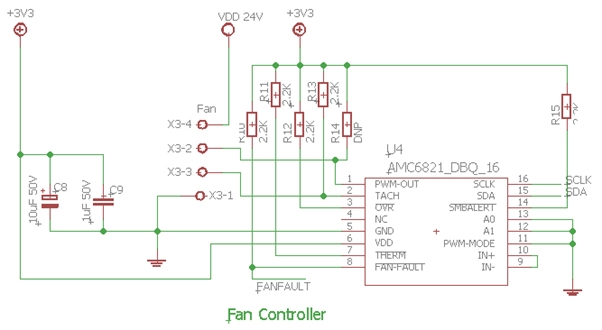
Is the IC faulty or something, or am I doing something wrong in using the i2c bus?  I have attached the circuit diagram below.

  • Chris,

    Do you have pull resistors for the I2C bus?
    Have you debugged your I2C code?

    -Kelvin
  • Hi Kelvin,

    Thanks for the prompt reply.

    Yes I have pull-up resistors on the I2C bus and I know that they are working, because I have other I2C devices on the same bus working correctly and I can also see data on the SCLK and SDA lines from a CRO.

    I am using the same basic i2c code I used on a MAX7318 i2c chip on the same board (which works), which is written in LabVIEW (same language you use for your AMC6821EVM Evaluation board - is this available for download?).

    The Master (microcontroller) sends the 8-bit register command for the Device ID Register (0x3D) and I then try to read one byte from this register (it should be the default value of 0x21), but it says there are no bytes available.

  • Hi Chris,

    Another item that would benefit the debug of you communication is to share an oscilloscope capture of the I2C transaction. Can you provide the readable I2C frame?

    Best Regards,
    Matt
  • Hi Matt,

    The attached CRO images is of me sending the Slave Address 0x18 and then the Command Register Address 0x3D (Device ID Register).  In my software I then also send the Slave Address again and the command to read this Register Byte.  However you don't see that on the CRO, because the first send receives a NACK indicating (I assume) that the AMC6821 didn't respond to this command.

  • We felt the temperature of the IC and it was 44c which was hot to touch - so we thought it might have been faulty.
    We replaced the IC and it immediately started to work as expected.
    I guess we were just unlucky :-(
  • After replacing the IC and before I connected up the 24Vdc 4-wire Sanyo 97BMB33_E fan, I checked the voltage on the fan PWM Input line to the fan and it measured 4V.
    Could this have damaged the IC (when connected to the PWM-OUT pin 1 on the IC), because VDD on the IC was +3.3V?
    From the data sheet the absolute maximum ratings is +6.5V so we are well within that, but I'm just wondering if this voltage, because it is higher than VDD will cause damage?
  • The PWM-Out is an open drain pin so I don't think a 4-V pull up voltage is a problem as long as the max sink current is less than 10 mA.
  • Thanks Kelvin,

    Yes it's all going well now (mostly anyway).  Software-DCY mode works fine, but it is open loop and there are no alarms if the fan stops working.

    Software-RPM mode is more complicated as it is closed loop, but it does give us alarms if the RPM level falls below a set level.

    However when we are reading the TACH-DATA registers (0x08 and 0x09) for some PWM settings we are getting considerable noise on the TACH input line.

    eg. for PWM = 75% we will get an RPM reading of say 7220RPM (TACH-DATA=831)  then all of a sudden it will jump to say 14,634 RPM - it appears very random.

    Funnily enough at PWM=100% there is very little noise on the TACH input line and the RPM readings are rock solid at around 8185RPM (TACH-DATA=733).

    How can we reduce the noise on the TACH input line for all PWM settings (ie. 0% to 100%) to obtain stable RPM readings?

    Chris

  • OK don't worry about the TACH input I've sorted that issue out.

    The last issue I have (hopefully) is simply how to turn the fan off in the event of an alarm (ie. fan stalls or something)

    On start-up I have set the registers as follows.  All other registers are left at their default.

    Config Register 1  -> 0x19 = Software-DCY mode
    Config Register 2 -> 0x07 = TACH/PWM enabled
    Config Register 3 -> 0x83 = leave as default
    Config Register 4 -> 0x88 = Set MODE to 1
    DCY Duty Cycle   -> 0x40 = PWM% is 25%
    TACH Low Limit (Low Byte) ->0xA0 = TACH Low Limit (Low Byte)
    TACH Low Limit (High Byte) -> 0x0F = TACH Low Limit (High Byte)

    I then read the FANS (bit 1) value from the Status Register 1 and when it is set to "1" (0x42) the fan has gone to slow and so I want to shut it down.

    To do this I then clear the PWM-EN (bit 0) value in the Configuration Register 2 and it does shut down the fan.

    However when I re-start the microcontroller (and after setting the registers as above) the fan immediately has a Status of (0x42) and shuts down - why is this happening?

    Chris

  • It seems I have an issue with writing to the Config Register 2.
    To turn the fan off I write 0x20 to this register to disable the PWM-EN bit.
    However when I repeat the above sequence of writing to the 7 registers - the Config Register 2 stays at 0x20 (it should have changed to 0x07).
    Even stranger if I write 0x82 to this register (ie. to set RST bit to "1" to reset the fan) it resets/crashes my whole microcontroller.

    Is there a particular order I should be writing the above registers in?
    Chris
  • Chris,

    Did you figure out the issue? Sorry for the late response.

    -Kelvin
  • More or less yes - thanks Kelvin.

    It turns out the IC was faulty and when we replaced it we could control it, albeit at a basic level.

    If I had more time I would look into the closed loop control of the fan, but for now we are just setting a PWM value and that does what we need for now.

    Chris