This thread has been locked.

If you have a related question, please click the "Ask a related question" button in the top right corner. The newly created question will be automatically linked to this question.

ADS1299: Ads1299 read data 4 time the same

Part Number: ADS1299
Other Parts Discussed in Thread: ADS1298,

Hi

I have an ADS1299 6channel on my board. Every thing looks fine. I can set register read register and read the data.If Icontroll with a sinus then I can see there are alwasy 4 sample with the same value.

This bad effect is with 1K, 2K but not with 250Hz or 500 Hz. I use rdatac.DRDY is 2kHz and gives a correct IRQ to the CPU . Even in the scope it looks correct timing. 

I would also like to ask if I have to read CH7 + CH8  when I use the ADS1299 6 Channel and what is the problem that I read 4time the same value

  • Hello Stefan,

    Thanks for your post and welcome to the forum!

    I'm not sure what you mean by "control with a sinus" can you explain that a little more thoroughly?
    Can you provide pictures to show the issue?

    What is IRQ?

    No, you do not have to read CH7 & CH8 when using the 6 channel version of the device.
  • Hello Alexander

    Thank you for the infos.

    IRQ means interrupt. It means the DRDY Pin.

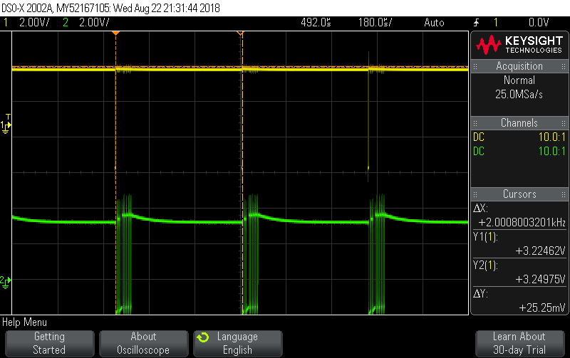
    The yello is the DRDY Pin, the green ist the spi read. it look ok.

    I used 50HZ Signalgenerator to test the channels.

    In the meantime I discovered the problem is only with channel 1,2, and3! Channel 5 and Channel 6 are ok

  • Thank you for the additional information!

    I'm still not understanding what exactly the issue is, are you referring to the "steps" that I'm seeing in your waveform?

    What is your input signal and PGA gain?
  •  Hello Alex

    Yes this steps are the problem, I use for all the 6 channel the same Gain (gain=1). On the analog input I connect a signalgenerator with 1Volt and 50Hz.So all the channel have the same signal. My sourcecode read all the channel in one go in a loop.So you can see the Channel1 (on top) is bad. Channel2 is ok, Channel3 bad .... 

  • Hi Stefan,

    What is the frequency of your SPI clock and how many pulses are being sent?

    This post is in regards to the ADS1298, however it may help: e2e.ti.com/.../2573727
  •  Hi Alex

    The samplefrequenz is 3.333mHz.

    I can not count the pulse so easy at the moment.

    If I chosse 500Hz sampling it's looks ok.

    I will read the anothe post...

  • Hi Alex

    I stil have the problem with the channel. Channel1;3;5;7 are bad if I sample with higher as 500Hz.

    In the meantime I have organized a second board and there I have the same problem. Do you have any idea what can I trie?
  • Hi Stefan,

    Apologies for the delay in my response. Did the post I linked help?

    What is the frequency of your SPI clock and how many pulses are being sent to collect data for every DRDY pulse?

    I think this is a software problem, not a board problem. If you have not already, I recommend reading section 9.4.4 of the datasheet to familiarize yourself with how the device handles data acquisition.
  • Hi Alex

    The clock from the SPI is 3.3MHZ

    I read the "section 9.4.4 of the datasheet"

    The strange thing is that with 500Hz every channel is ok.

    With 2000Hz every second channel look as it is still in 500hz mode. But this is not possible.
    Are there some register there are not in the datasheet?
    I think I can not config this strange mode.....


    Best regards

    Stefan
  • Hi Stefan,

    Can you please answer my question of how many SPI CLKS are you sending after the DRDY pulse?

    If you're sending too many or too little (which is what I suspect is happening) then the data can be corrupted.

    No, there is not a hidden register that is not shown in the datasheet.
  • Hi Alex

    I count it all..... 21*8

  •  Hi Alex

    I count them all..

    It's 21*8 clock.

     On the second picture

    I sweep the frequence

    from the analoggenerator

    and it looks as if channel1,3,5,7 can not sample higher frequencies.

  • Hi Stefan,

    Apologies for the delay, it was a holiday yesterday in the US.

    Thank you for providing the number of SCLKs being sent.

    As per section 9.4.4.2 of the datasheet:

    "The number of bits in the data output depends on the number of channels and the number of bits per channel. For the 8-channel ADS1299, the number of data outputs is [(24 status bits + 24 bits × 8 channels) = 216 bits]. The format of the 24 status bits is: (1100 + LOFF_STATP + LOFF_STATN + bits[4:7] of the GPIO register). The data format for each channel data are twos complement and MSB first. When channels are powered down using the user register setting, the corresponding channel output is set to '0'. However, the channel output sequence remains the same."

    Try increasing the SCLK frequency and the number of pulses being sent!

  • Hi Alex

    Befor you informed me like this.....
     No, you do not have to read CH7 & CH8 when using the 6 channel version of the device.

    Also about the SPI clock I read something different.....

    9.5.2.2 Serial Clock (SCLK)

    For example, if the ADS1299 is used in a 500-SPS mode (8 channels, 24-bit resolution), the minimum SCLK

    speed is 110 kHz.

    I will try to increase the clock and also read channel 7 and 8

    regards

    Stefan

  • Hi Stefan,

    I gave you some incorrect information on a couple accounts.

    Since 50nS or 66.6nS is the minimum SCLK period, that corresponds to 20MHz or 15MHz for the maximum speed for SCLK depending on DVDD voltage. I got mixed up thinking that we found the issue!

    I forgot that you're not using Ch7 & 8, sorry about that! 168 should be fine, however sending extra SCLKs should not hurt as long as your code can split the new codes out and discard them accordingly.

    Where does the 21*8 calculation come from since 8 does not correspond to number of channels?

    Can you post your code showing how the output codes are being converted? I still think that this looks like a data corruption issue.
  • Hi Alex

    Sorry the 21*8 means 21*8bit, 3*8bit staus and 6*3*8bit data.

    For the sourccode I used Flowcode 8 from Matrix.

    (Flowcode is an advanced integrated development environment (IDE) for electronic and electromechanical system development targeting microcontrollers such as Arduino, PIC and ARM)

    In the interrupt I read the 3 status register Byte and to nothing with them....

    and the 18 Byte from the channel I put first an array and then in a buffer. This buffer I flush to a micro-sd card.

  • Hi Alex

    Here  I have printed out the 23 register from the ADS1299  

    I hope I set it correct

  • Hi Alex

    Only the 4 config register

  • Hi Stefan,

    Thanks for the background and introduction to your coding scheme!

    I'm not familiar with flowcode, so I do not have insight in to the specific functions.

    Your registers look fine, I did not see anything obvious that would explain this issue.

    The symptoms look like data corruption, I think that a byte is being shifted, or repeated in some way. One thing that I noticed is that you have repeatx3 for discarding the status byte, this is similar to your "stepping" where you see a correct output, followed by 3 dead codes. Could this be related if there is an incorrect step somewhere? I'll have to think on your method and learn a little more about flowcode.
  • Hi Alex

    Thank you for controlling the register.

    With 500Hz every thing is ok. Maybe I dont mix bytes.It looks more an timing problem.Or a serious problem from the ADS1299 -6

    Can you have a look why Channel 1,3,5 are together as a problem? Or why the another 3 channels are ok?

    Maybe if I know Channel 1,3,5 is sampled first or last I have a little more info.

    regards

    Stefan

  • Hi Stephan,

    Happy to help and sorry that we're having issues getting your design up and running!

    Looking back at our old posts:

    Originally Ch1,2,3 were bad and Ch5&6 were OK.
    Then Ch 1, 3, 4, & 5 are bad from a screenshot of the waveforms.
    Now it's Ch 1, 3, 5, & 7(N/A)....

    It is possible that your ADS1299-6 has been damaged, if you have a replacement available I would recommend switching it out.

    However, due to the nature of the output waveforms I think it's a timing/code problem. It may help to try 1 channel at a time as opposed to all 6.

  • Hi Alex

    In the meantime I have tested 3 different boards and always the same problem.
    I have attached to the 3 channels 2,4,6 electrodes and made a record. This record was good. I would like to use this IC already.

    Yes at first it was different with the channel.But I'm not 100 percent sure

    After I made my software more stabel and more comfortable to show the channel nicely

    it is always Channel 1,3,5 bad  and Channel 2,4,6 good

    So there is a different in the way I read in the interrupt as it should be according to data sheet

    On beginn I put the chipselect to low, read all the Byte and the I put the chipselect to high.

    I changed this like "9.5.3.7 RDATAC: Read Data Continuous" and let it always low.

    The result is that Channel 1,3,5 are just 0 and Channel 2,4,6, still  good.

  • Hi Stefan,

    Since this problem is consistent across boards it's good to know what it is not this individual chip that is having issues.

    What happens if you test each channel individually?

    If Ch 1,3,5 are always 0 then maybe we're looking at a layout issue. If so, please post a picture of your layout.
    Ch 2,4,6 still look a little choppy, but that depends on sampling rate and such.
  • Hi Alex

    Yes it is not the problem of one chip.

    No I dont think it's a layout problem. If I sample with 250Hz and 500Hz it look ok. But if I sample with 1k or 2k it's strange. 

  •  Hi Alex

    I tried with the intern testsignal.

    At the picture left is normal view.

    At the picture right is zoom view.

    This looks not good for channel 1,3,5

    4 times the same value....

  • Hi Stefan,

    I agree that your layout looks fine.

    As I have recommended a few times, I would try testing each channel individually to rule out physical defects in the channels.

    After that I would take a long look at your code and try to figure out what the problem is. I think that a loop is incorrectly written which causes the data to be repeated multiple times. This makes me think that the data is not being cleared successfully and is just being re-written.
  • Hi Stefan,

    In your code, are you discarding bits at any point?

    I see a note that says "7-8 bits not used"

    If these bits are somehow being thrown away it would explain why you're seeing the repeated outputs.

    Also, keep lead off detection disabled for now.
  • Hi Alex

    I rely on it when you say that I do not need to read channel 7 and channel 8 ...

    I disabled lead off detection.

    It's not helping. Still channel1,3,5 are bad.

    I controlled comunication signal  with the osciloscope.

    You can see:

    at first left yellow=Interrupt; green=clock; at right side in an another timebase

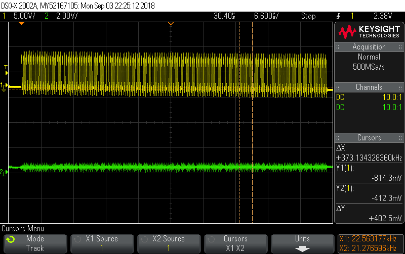
    at second  left yellow=Interrupt; green=chipselect; at right side in an another timebase.

    I think the signals are correct but half of the channels are not ok.

    Do you have a hardware with the ADS1299-6?
    Could you please test with the internal test signal if channel are ok with 2kHz?

  • Hi Stefan,

    I did not realize from the code comments that that was in regards to channels 7 and 8. However I think you should take a long look at your code and investigate to see if this is related to the problem. There is most likely an error in your loop at some point that is resulting in bits being discarded, and the output code being repeated.

    I do not have an ADS1299-6 specifically, however I have an ADS1299 and it runs just fine.

    Is there a reason you cannot test each channel individually?

  • Hi Alex

    I testet just channel 1 with my generator. The signal was bad. (this 4 times the same value)

    Or do you mean I dont read all the channel with the SPI for a trial? just one?

  • Hi Stefan,

    Yes, I mean to just read 1 channel at a time with SPI. You will have to change your code.
  • Hi Alex

    Looks first time bether...


    If I read Channel 1 => Channel 1 is ok !
    If I read Channel 1 + Channel 2 => Channel 1 is ok Channel 2 is ok
    If I read Channel 1 + Channel 2 + Channel 3 => Channel 1 is bad Channel 2 is ok Channel 3 is bad


    How can I solve it?
  • Hi Stefan,

    Now that we have ruled out physical defects in the channels, you have to debug your code and find out where the issues are coming from.
  • Hi Alex

    Yes, that's good.

    Only I have no idea what to do.

    I tried delays, tried clock faster and slower, controlled all siganl with osciloscope.

    Do you have a little help for that? A tip ...

    regards and thank you for all the help you already did.

    Stefan

  • Hi Stefan,

    You are welcome.

    Please read my posts on the previous page.

    This issue is due to data being transferred incorrectly. There is an issue with either codes being incorrectly discarded, codes being repeated, improper addresses, etc... any of these could explain why the data is being corrupted in between the device and the output waveform.

  • Hi Alex

    To read 2channel is working and if I read more channels then the first channel  becomes bad.

    So I tried to read just 2 channel and give clock for the another 4 channels. It's still bad.

    Then I had a good idea. I startet the first minutes with two channel then next minute with  6channels and then again with 2 channels.

    The result was that the first minute the  both channels are good

    in the second minute the first  channels was bad.

    and in the third minutes the first channel was still bad even it's the same reading as in the first minute!

    So thats means if it's ones bad, it's for the rest of the recording bad, even it's back to read just 2channels.

    Do you have an explanation why the ADS1299 gets confused? Reading the complet number of bits let it crash?

  • Stefan,

    I do not think any positive results will come from testing like this.

    There is an issue in your code that needs to be fixed.

    The ADS1299 is not getting confused or crashing.