


Dear ,
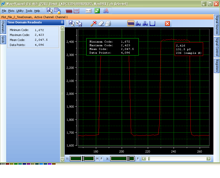
As the attachment show in WaveVision 5 tool .
What's mean about 4095 counts in Y-axis ? is voltage level or what ?
How should I calculate the frequency of the signal ?
Best Regards,
Jean
Dear ,
As the attachment show in WaveVision 5 tool .
What's mean about 4095 counts in Y-axis ? is voltage level or what ?
How should I calculate the frequency of the signal ?
Best Regards,
Jean


