This thread has been locked.

If you have a related question, please click the "Ask a related question" button in the top right corner. The newly created question will be automatically linked to this question.

How to synchronize ADS42JB69 EVM w/ JESD204B

Other Parts Discussed in Thread: ADS42JB69EVM, LMK04828, ADS42JB69, DAC37J84EVM, ADS42JB46

Hi expert,

My customer try to use following set to capture waveform.

* ADS42JB69EVM

* TSW14J10EVM

* Kintex KC705

(Please see "Figure 1. TSW14J10EVM, ADS42JB69EVM, and Kintex KC705 Development Card" of http://www.tij.co.jp/jp/lit/ug/slau580/slau580.pdf about detail)

Question :

They try to synchronize b/w two boards such as page 11 of slau580.pdf.

However, even though they put SW7(Reset button) of KC705, they could not observe synchronization b/w two boards.

Is there any method which is not described in document ?

Could you please give me any point which they have to be careful ?

Best Regards,

Machida


  • Machida,

    After programming the ADS42JB69EVM, what is the status of LED's D9 and D7? These both need to be on. After downloading the firmware to the KC705, what is the status of the GPIO LED's 0-7, located at the top right of the KC705? This will help me with trouble-shooting the issue.

    Regards,

    Jim

  • Machida,

    Make sure the customer has the GTX and core clocks enabled on the ADS42JB69EVM GUI. The LMK04828 GUI page should look as the one attached.

    Regards,

    Jim3644.LMK04828.pptx


  • Hi Jim,

    I'm sorry for delay reply. Since I can not enter my account now, so I use another account for only this post.
    Here is answer from customer about below.

    Q1. What is the status of LED's D9 and D7 ?
    A1. Following the ADS42JB69EVM's LED status

    D9 : OFF
    D7 : OFF

    Q2. What is the status of the GPIO LED's 0-7, located at the top right of the KC705 ?
    A2.
    LED0 : OFF
    LED1 : OFF
    LED2 : ON
    LED3 : OFF
    LED4 : OFF
    LED5 : Blinking
    LED6 : OFF
    LED7 : Blinking

    Q3. Make sure the customer has the GTX and core clocks enabled on the ADS42JB69EVM GUI.
    A3.
    I didn't use ADS42JB69EVM GUI. (High Speed Data Converter Pro - Only)

    ADS42JB69EVM GUI is included  variety settings of LMK04828 and ADS42JB69.
    HSDC Pro also includes a variety of settings.

    I wanna check the operation by using a sample settings of ADS42JB69EVM GUI and High Speed Data Converter Pro.
    Please tell me the combination of settings.

    Best Regards,

    Machida

  • Machida,

    The customer is not programming the ADS42JB69EVM properly. LED's D9 and D7 must be on for synchronization to occur. Please have them follow the steps in the attached User's Guide.

    Regards,

    Jim

  • Hi Jim,

    >Please have them follow the steps in the attached User's Guide.
    Which document do you indicate ?

    Best Regards,
    Machida

  • The ADS42JB69EVM User's Guide. Go to www.ti.com and enter "ADS42JB69EVM" in the search window. This will take you to the product folder where you can download this file. This was attached in my last response.

  • Hi Jim,

    I'm sorry to re-open this thread, but let me confirm one thing about your test condition.

    * I believe that you used following two tools to test "ADS42JB69 EVM + TSW14J10 + KC705".

    1. ADS42JBx9 GUI

    2. High Speed Data Converter Pro

    In above conbination, did you use only following two files to test function ?

    * ADS42JB69_LMK04828_settings.txt

    * TSW14J10_KC705.svf

    Best Regards,

    Machida

  • Machida,

    The ADC GUI used the file attached. CLKout 0 &1, 2 & 3 and 8 & 9 should all be enabled.

    Regards,

    Jim

    5611.ADS42JB69_EVM_LMF421_250M.cfg

  • Hi Jim,

    Thank you for your reply.

    I understood your explanation as show below.

    User should set ADS42JB69 GUI by referring to section 3.3.4 of "slau467a".

    However, when user will perform test which use KC705(TSW14J10_KC705.svf) w/ TSW14J10, user should use "5611.ADS42JB69_EVM_LMF421_250M.cfg" instead of "ADS42JB69_LMK04828_settings.txt".

    Is my understanding correct ?

    Best Regards,

    Machida

  • Machida,

    The .txt file is to be used with the older version of the GUI, called "ADS42JBx9 GUI". The .cfg file is to be used with the the newer version of the GUI called "ADS42JBxx EVM GUI". Either config file will work with the KC705 board.

    Regards,

    Jim

  • Hi Jim,

    Thank you for your reply.

    I believe that "ADS42JBxx EVM GUI" is not released officially. Is my understand correct ?

    And, in case of  testing ADS69JB49EVM and DAC37J84EVM, you also use "TSW14J10_KC705.svf" for KC705 board ?

    Best Regards,

    Machida

  • Hi Jim,

    Could you please give me your feedback ?

    Thanks in advance,

    Machida

  • Machida,

    Yes, you can use the TSW14J10 and KC705 to test both the ADC and DAC boards you mentioned.

    Regards,

    Jim

  • Hi Jim,

    Thank you for your reply. I understood.

    By the way, my customer has not worked "ADS42JB69 + TSW14J10 + KC705" correctly yet.

    So, let me confirm following questions.

    1. Is there any specific board Rev to work correctly, by any chance ?

        My customer use "TSW14J10 is RevB" and "ADS42JB69EVM RevD"

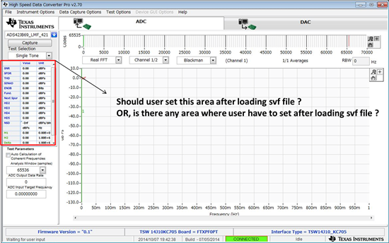
    2. Could you please confirm question which is included following captured image ?

    Best Regards,

    Machida

  • Machida,

    After loading the svf file, go to the bottom and enter the sampling rate. Make sure the ADC was programmed, LED's D4 and D1 are illuminated on the ADC EVM, and the user clicked on "SYNC" of the tab labeled "LMK04828 Outputs". The LED's on the KC705 should match the condition stated on page 12 of the TSW14J10 User's Guide. If all of these condiotns have been meet, click on "Capture" of HSDC Pro GUI and you should get a valid capture.

    Regards,

    Jim  

  • Hi Jim,

    Thank you for your reply.

    >If all of these condiotns have been meet, click on "Capture" of HSDC Pro GUI and you should get a valid capture.

    Does mentioned above mean even though user do not set certain test pattern, KC705 can capture signal generated by ADC42JB69 ? 

    Best Regards,

    Machida

  • Machida,

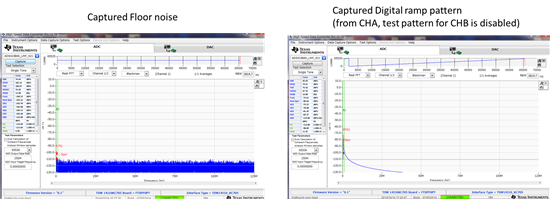
    The KC705 will capture data and show just the noise floor of the ADC if there is no test pattern or input data from the ADC.

    Jim

  • Hi Jim, Which test pattern did you use to test this combination ? Because, it seems that there is sample test pattern ? Did you use pattern or signal generator from out of ADS42JB69 EVM ? If there is file to generate test pattern,could you let me know ? Best Regards, Machida
  • I used the ADC internal ramp pattern generator. 

  • Hi Jim,

    Thank you for your reply.

    >I used the ADC internal ramp pattern generator.

    Is there any document or section about how to use internal pattern generator ?

    Because below is what my customer want to do.

    "We want to capture waveform by using ADC internal pattern generator"

    By the way, as first step, customer could capture floor noise.

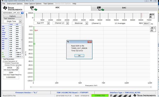
    But, even though they used ADS42JB69 EVM, they could capture waveform by using "ADS42JB46_LMK0428_settings.txt"  instead of "ADS42JB69_LMK04828_settings.txt"

    When they used "ADS42JB69_LMK04828_settings.txt", they could see time out as shown below.

    Do you know why this phenomenon appeared ?

    Best Regards,

    Machida

  • Hi Jim,

    -0-

    I could avoid "time out" error by performing following procedure.

    1. Power on TSW14J10 by USB
    2. Power on ADS42JB69 EVM by AC adapter.
    3. Press Reset switch(SW1) of ADS42JB69 EVM.
    4. Power on KC705 EVM by AC adapter.
    5. Launch HSDC Pro and load "TSW14J10_KC705.svf".
    6. Launch ADS42JB69 GUI and load "ADS42JB69_LMK04828_settings.txt" to send register value.
    7. Perform "SYNC" on ADS42JB69 GUI
    8. Set "ADC output Data Rate" to 250M on HSDC Pro.
    9. Press CPU_RESET(SW7) of KC705 EVM
    10. Perform "Capture" on HSDC Pro
    * When I skip procedure "3", I observed "time out" error.
    ADS42JB69 is NOT performed "RESET" during power on sequence ?

    -1-

    I could capture test pattern by using "Digital ramp" test which is included Digital Block of ADS42JB69.

    Does below mean above test ?

    >I used the ADC internal ramp pattern generator.

    Best Regards,

    Machida

  • Machida,

    Yes. What you did is correct. The GUI configuration file you used does not write to all ADC registers so you must do a RESET after power up.

    Jim

  • Hi Jim,

    >The GUI configuration file you used does not write to all ADC registers so you must do a RESET after power up.

    I understood.

    >I could capture test pattern by using "Digital ramp" test which is included Digital Block of ADS42JB69.

    >Does below mean above test ?

    >>I used the ADC internal ramp pattern generator.

    How about above question ?


    I would like you to confirm about following point.

    * When I performed procedure from 1 to 10 which I posted on previous thread, I have never seen illumination of D3(JESD_SYNC) on ADS42JB69 EVM.

    Have you seen same phenomenon on your test ?

    Best Regards,

    Machida


  • Machida,

    What version of HSDC Pro GUI are you using? Is the captured data valid? The version of firmware you are using on the KC705 may not have this signal assigned. This may have been an older version of firmware Xilinx did for us.There is a SYNC LED indicator on the KC705. What is the status of this? This is LED 1. 

    Jim

  • Machida,

    I was able to duplicate what you are seeing when running version 2.7 of HSDC Pro GUI. The next version to release of HSDC Pro will correct this issue and D3 will illuminated when synchronized.

    Jim 

  • Hi Jim,

    >What version of HSDC Pro GUI are you using?

    A. v2.70

    >Is the captured data valid?

    A. I captured following two case.

        1. Just Floor noise

        2. Digital Ramp pattern which can be generated Digital block of ADS42JB69 EVM


    >What is the status of this? This is LED 1.

    A. Before clicking on "Capture" button, I saw

    GPIO LED on KC705

    LED0 : OFF

    LED1 : OFF 

    LED2 : ON

    LED3 : OFF

    LED4 : OFF

    LED 5 -7 : Blighting

    After clicking on "Capture" button, I saw

    GPIO LED on KC705

    LED0 : OFF

    LED1 : ON

    LED2 : OFF

    LED3 : ON

    LED4 : OFF

    LED 5 -7 : Blighting

    Best Regards,

    Machida

  • I am using v2.70.

    The capture is valid. Do you have an analog input connected? If so, make sure you are looking at the channel that has this input.

    LED 1 will indicate ADC sync has been established when "ON".

    Your ramp data capture plot looks fine. If you switch to Time Domain you will see a better represenatation of the ramp.