This thread has been locked.

If you have a related question, please click the "Ask a related question" button in the top right corner. The newly created question will be automatically linked to this question.

ADS5404 Firmware for TSW1400

Other Parts Discussed in Thread: ADS5404, ADS5400, ADS5402, ADS5401

Hello,

A while back I was given access to firmware source code for the ADS5404 and TSW1400. It was given to me by Jim Seton in this thread. The firmware project is title 'golden trigger'. It is clear this firmware was designed to work with many different ADCs. 

I'm aware TI doesn't support custom firmware, but I'm hoping to get started getting the base firmware to work properly. Once I get to that point, I can make modifications on my own- but currently it's not functioning properly. I can compile the firmware and load it on the FPGA, but the output to HSDC Pro is useless- there is no semblance of the signal left. Here is what I've done:

HSDC Pro Included Firmware + 15 MHz ChA Signal + 500 MHz ADC Clock signal

The configuration above functions properly and I can see the 15 MHz signal in HSDC Pro. However, in the following configuration I get nothing:

TI 'golden trigger' firmware loaded with HSDC Pro + 15 MHz ChA Signal + 500 MHz ADC Clock signal

I can send a capture command, and it is pulling something, but it appear to be just noise. There are a few things I made sure were set in the defines.vh file, but they did not fix my issue. First, I have:

'define     ADC_BM0     'ADS5400_BMO

For the bus, I currently have:

'define     BITWISE_DDR_2W_12B  

I chose that as I have a 12-bit ADC. Apart from that, I'm not sure which one I'd like to have defined (and I've tried each and every one individually).

If anyone familiar with this firmware could get me at least to the point where the base firmware was functioning properly, it would be appreciated! If there is base firmware specifically for the ADS5404 that works out of the box, that would be okay too!

Thank you for all of your wonderful help thus far, TI!

Nicholai

  • Nicholai,

    In the defines file, set the bus to SAMPLEWISE_DDR as this is a parallel bus output. Set the ADC_BM0 to ADS5402 as this device has the same output format as the ADS5404.

    Regards,

    Jim

  • Jim,

    Thank you for your reply. However, the reason I set it to ADS5400 is there is no defined case for the ADS5404 or ADS5402 in the adcif.v file. As a result, when we get to that case statement, we just fall into the default rx0a_in and mask. In the second case statement, we again see there is no case set up for the ADS5402 or ADS5404- just the ADS5400. Perhaps I have an older version of the file?

    I did try the following in the define file:

    `define     ADC_BM0     `ADS5402_BM0

    `define     SAMPLEWISE_DDR

    No other changes are made to the define file. Upon compilation and converting to an .rbf, the data into HSDC Pro is still just noise (noise not being the best term). Perhaps one of the other settings in the file are not what they should be. Should "DUAL_BUS_ADC" be defined or not, as there are parallel busses? Also, is there any reason I might need to change the FIFO width or channel width?

    PS: For my own knowledge, what does BM0 stand for?

    Thank you for your help so far, Jim

    Nicholai

  • Can I manually enter a case statement for the ADS5402, or is there firmware available for either the ADS5404 or the ADS5402?

  • Bump. If anyone knows of a solution to this, it would be appreciated.

  • Still looking into this.

  • I apologize, Jim, I did not know you were still looking into it. I'm just trying to make sure I wasn't left by the wayside!

    Thank you for your help thus far!

    Nicholai

  • 3175.ADS5402_totest.qar

    Nicholai,

    This is what we got from our firmware development team.

    Regards,

    Jim 


  • Jim,

    Thank you for the reply. Looking at the project, there is now a case statement for the ADS5402, and it can be properly defined in defines.vh. I have compiled the project and burned it to the TSW1400. However, I am still getting a bad output when using HSDC Pro. Below is a capture using the included firmware from HSDC Pro. The output is correct- I am supplying a 3.54 MHz sine wave.

    However, if I burn the firmware created from the Quartus project attached above, this is the output when using HSDC Pro:

    Note- there were no changes to the hardware setup between trials, and no changes to the Quartus project file (The defines were already set).

    I hope I'm missing something simple here?

    Again, I am truly thankful for you tracking down the firmware for me. If it is easier for you, and at all possible, I would not mind talking directly to the firmware team?

    Nicholai

  • Nicholai,

    If you send us your firmware, we can take a look at it to see if there is something wrong or missing.

    Regards,

    Jim

  • Jim,

    The firmware in the second picture (not working) is the firmware you sent me, compiled without changes in quartus. The firmware in the first picture (functioning) is just the firmware included in the HSDC Pro installation.

    Nicholai

  • Nicholai,

    We got this working with the attached project.

    Give this a try.

    Regards,

    Jim

    8078.ADS5404_working.qar

  • Jim,

    Thank you for your reply, and please extend my gratitude to the firmware team. However, I haven't quite gotten this to work yet. I have tried compiling this directly, and am having the same problem. The HSDC Pro firmware works, but the compiled project does not. Are there any special considerations I need to take when working with your firmware project? Do I need to supply a clock somewhere that I don't need to for the HSDC Pro firmware? This is my setup:

    1. ADF4351 provides a 500MHz clock into the ADC
    2. Function generator at 12.5Mhz, 400mVpp offset sine wave to Channel A on ADC
    3. TSW1400 phsyically to ADC, USB to PC running HSDC Pro v3.00.

    Here is the process:

    1. Power to TSW1400, ADF4351, and ADS5404.
    2. ADF4351 set to 500MHz output.
    3. Connect to the TSW1400 via HSDC Pro.
    4. Create a 12.5MHz signal source on the function generator to measure with the ADC.
    5. Upload pre-packaged firmware for the ADS5404 onto the TSW1400.

    This gives me the following output, as expected:

    From here, I then download the new firmware (ADS5404_5F00_working.qar) which I compiled and created an rbf out of (note- no changes were made to the project). Also note, I did not close and reopen HSDC Pro. Uploading this new firmware with no changes made to the clocks or the signal source gives me this:

    Note, this is similar to the other capture, in that I'm not seeing anything useful. If this was working for you, I wonder- does your setup require any additional clocks or special signals? Do I need to use the ADS5404 program to configure the ADC in a way other than default for the firmware to function?

  • Was there ever an answer back why the firmware was not functioning while the HSDC Pro firmware was, with no changes in setup?
  • Nicholai,

    Due to limited resources, this issue has not been resolved. What is your current situation? We may have help available now to look into this.

    Regards,

    Jim

  • Jim,

    Thank you for the quick reply. My current situation is the source firmware given to me for the ADS5404, when compiled (without changes to the code) and burned to the device with HSDC Pro, does not give me good output, while the firmware included in HSDC Pro for the device does. Both setups being exactly the same, tested within minutes of one another.

    I'd very much like to develop firmware for the ADS5404, however, if the source firmware directly from TI doesn't work, I don't have much of a starting place.

  • Nicholai,

    You will need to use a new ini file with HSDC Pro if you are using the new firmware we sent.ADS540x_NEWqar.ini

    I have attached this file. Follow the instructions below. Then replace the .rbf file that this ini will load with your new one and use the same naming convention.

    Regards,

    Jim,

    The firmware that I had sent was alright but the ini file that had to be used was different. There is a change in channel pattern order. I have attached the new ini file and also the rbf file, that I had sent before. Gokul has tested this and verified that the default firmware and this firmware gives the same ADC codes and SNR/harmonics.

    User needs to put the ini file in the HSDC pro ini folder ( C:\Program Files (x86)\Texas Instruments\High Speed Data Converter Pro\1400 Details\ADC files ) and has to ensure that he selects this ini file and does not download the default HSDC pro firmware when it is asked for. He has to download the firmware that was sent earlier or the firmware that is attached with this mail.


  • Jim,

    I hate to resurrect an issue that hasn't been touched in a while. We had stopped working with the board a while back due to the unresolved issues. Recently, however, we decided to take another look at using this board, as we have it, and it would be very nice if we got to a point where we could develop to it. At this point, we still have not been able to get any of the pre-packaged Quartus projects to function properly in HSDC Pro, even with the new ini. Just to recap, this process works:

    1. Connect ADC to TSW1400
    2. Connect a 500MHz reference clock.
    3. Connect a signal to measure, 15MHz from signal generator.
    4. Connect to the board using HSDC Pro
    5. Download the included firmware and ini using ADS5401-09
    6. Set the sample rate to 500M.

    This process correctly captures the 15 MHz input signal. Now, we want to develop to this board, so we want the base code to work, and we can adjust the code from there. This is the process:

    1. Download the 8078.ADS5404_working.qar project you gave to me.
    2. Open in Quartus. No changes made to code. Synthesize, Fit, and Assemble.
    3. Convert the programming file to RBF.
    4. Add the new .ini file to the HSDC Pro folder (C:\Program Files (x86)\Texas Instruments\High Speed Data Converter Pro\1400 Details\ADC files)
    5. Add the new RBF file to the firmware folder (C:\Program Files (x86)\Texas Instruments\High Speed Data Converter Pro\1400 Details\Firmware)
    6. Make sure the new .ini links to the name of the new firmware.
    7. Start HSDC Pro, and make all the same connections as before.
    8. Select the new .ini from the drop down list, and select the new, unchanged firmware.

    Here, we still get complete noise, not capturing the 15 MHz signal. For reference, this is our .ini file:

    [ADC]

    Interface name="ADC_0519_2015_v2"
    Number of channels=2
    Channel Pattern=2,1,2,1,2,1,2,1
    Data Postprocessing=2:4095,1:2047
    \\ firmware inverts data bits to account for firmware.
    \\ msb not inverted to set up for 2's complment format.
    \\
    Number of Bits=12
    check_fclk=0
    srf=1
    df=1
    adc_type=0
    adc_check=0
    Max sample Rate=800000000
    fclk_code=0
    config1=56
    config6=0
    config7=0
    Read EVM Setup Procedure="EVM Setup Procedure not available"
    \\use <> as delimiter for newline

    The only change is the name of the ADC file, which matches our firmware name exactly, as placed into the firmware folder above.

    If you are still willing to work on this issue, it is appreciated. I really am not sure how the firmware team at TI is getting this to work, if we truly are using the same files.

    Thanks,

    Nicholai

  • Nicholai,

    We built the Qar file given in your post, generated RBF file and tested with ADS5402. It is working fine.  We are attaching the RBF(ADS540x_NewQar.rbf) and INI(ADS540x_NewQar.ini) that we tested with this mail. Please keep RBF file in Firmware folder and INI in ADC files folder. Select the INI(ADS540x_NewQar) in HSDC Pro after connecting to board. Make sure the new RBF is loaded. Otherwise, load manually through Instrument Options->Download Firmware. Perform a capture and let us know if it works.

    It this RBF works in your setup, there must be a problem in creating RBF file on your side. It it does not work, there must be a difference in the setups.new files.zip

  • Thank you for your reply Jim. Sorry for the delay on my end, as I only have time to work on this project on weekends.

    Anyway, the linked files do work. Subbing in the attached .rbf for my generated .rbf causes the ADC to no longer work. So, the only answers I can think of are:

    1. The software team is working from a modified version of the 8078.ADS5404 project.
    2. There is an issue during generation of the .rbf file.

    First, I want to attach the defines file being used, just in case I need to make a single, small change to it. Note, I added the .txt extension simply because I was getting an error with the .vh extension.

    defines.vh.txt
    `define	adly					1
    
    `ifdef	USE_SMALL_FIFO
    	`define	FIFO_ADDR_WIDTH		5
    `else
    	`define	FIFO_ADDR_WIDTH		15	// <-- 256K
    `endif
    
    `define	CHNL_DWIDTH				16		// defines number of DDR inputs per ADC
    `define	MSPI_FRAME_SIZE_BYTES	2'd2	// <-- remove this options eventually
    `define	SS_DEASSERT_WAIT		4	// wait SS_DEASSERT_WAIT sys_clk cycles before asserting-
    									      // de-asserting SS after last cycle of spi_clk
    
    `define	CONFIG0_DEFAULT			{8{1'b1}}
    `define	CONFIG1_DEFAULT			8'h0
    `define	CONFIG2_DEFAULT			8'h0
    `define	CONFIG3_DEFAULT			8'h0
    `define	CONFIG4_DEFAULT			8'h0
    `define	CONFIG5_DEFAULT			8'h0
    `define	CONFIG6_DEFAULT			8'h0
    `define	CONFIG7_DEFAULT			8'h0
    `define	CONFIG8_DEFAULT			8'h0
    `define	CONFIG9_DEFAULT			8'h0
    `define	CONFIG10_DEFAULT		8'h0
    `define	CONFIG11_DEFAULT		`INTERFACE_ID
    `define	CONFIG12_DEFAULT		8'h0
    `define	CONFIG13_DEFAULT		8'h0
    `define	CONFIG14_DEFAULT		`FIRMWARE_VER
    `define	CONFIG15_DEFAULT		`ADC_BM0
    
    `define	IPLL_DEFAULT_ROM		2'b00  //2'b11  chnaged by prakZ
    
    `define	MAXIMUM_ROWS		16'h3FFF
    `define	MAXIMUM_COLS		10'h3F8
    `define	MAXIMUM_BANKS		3'd7
    `define	MAXIMUM_CHIPSEL	1'b0
    
    `define FIRMWARE_VER 	8'd2  // Rev 2  6-10-12
    
    `define INTERFACE_ID 	8'd16 //5296 16bit
    
    `define	TB_BM0				8'd0
    `define	ADS62P49_BM0		8'd1  //ADC_BYTE_WISE_2CH (14B. ADS62P29 is 12B)
    `define	ADS4249_BM0			8'd1  //ADC_BYTE_WISE_2CH (14B. ADS62P29 is 12B)
    `define	ADS5400_BM0			8'd2  //ADC_SAMPLE_WISE (12B)
    `define	ADS54RF63_BM0		8'd2  //ADC_SAMPLE_WISE (12B)
    `define	ADS5474_BM0			8'd3  //ADC_SAMPLE_WISE (14B)  
    `define	ADS6445_BM0			8'd4  //ADC_2W_14b (4CH)
    `define	ADS6425_BM0			8'd5  //ADC_2W_12b 
    `define	ADS5493_BM0			8'd6  //ADC_4W_16b
    `define	ADS5459_BM0			8'd6  // ???
    `define	ADS5281_BM0			8'd7  //ADC_1W_12b
    `define	ADS58C48_BM0		8'd8  //ADC_BYTE_WISE_2BUS (4CH DUAL_BUS_ADC enabled)
    `define	ADS5485_BM0	   	8'd9  //ADC_BYTE_WISE_1CH (16B)
    `define	ADS4149_BM0			8'd9  //ADC_BYTE_WISE_1CH (14B & 12B)
    `define	AFE5808_BM0			8'd10 // addition by PrakZ
    
    //`define	ADS6445_14b_BM0	8'd15 //ADC_2W_4CH (14B & 12B) 
    `define	ADS58H40_BM0		8'd14 //ADC_SAMPLE_WISE_4CH (DUAL_BUS_ADC enabled)
    `define  ADS5294_BM0			8'd15  // added by PrakZ
    `define  ADS5296_BM0			8'd16
    
    `define	ADC_BM0			`ADS5400_BM0
    
    `define	SAMPLEWISE_DDR
    //`define	BYTEWISE_DDR
    //`define	BITWISE_DDR_2W_12B
    //`define	BITWISE_DDR_2W_14B
    //`define	BITWISE_DDR_2W_16B
    //`define	BITWISE_DDR_4W
    //`define	BITWISE_DDR_1W
    
    //`define	BITWISE_DDR_1W_10B
    //`define	BITWISE_DDR_1W_12B
    //`define	BITWISE_DDR_1W_14B
    //`define	BITWISE_DDR_1W_16B
    
    
    `define	DUAL_BUS_ADC	// ADC Bus Width is greater than 16
    
    `define	TB_BM1			64'hFFFF_FFFF_FFFF_FFFF
    `define	ADC_BM1			`TB_BM1
    
    
    //Latest IID file copy
    
    /*
    14,ADC_SAMPLE_WISE_4CH
    16,ADC_SAMPLE_WISE_2CH
    17,CMOS_MSB_0SKP
    18,CMOS_LSB_2SKP
    19,AFE5808_09_16b
    20,AFE5808_09_12b
    21,ADC_5294_1W_14b
    22,ADC_5294_1W_12b
    23,AFE5808_09_14b
    24,ADC_5296_10b
    25,ADC_5296_12b
    26,ADC_5296_14b
    27,ADC_5296_16b
    
    */

    And briefly talk about the creation of the .rbf. Currently, this is the process.

    1. Run Analysis & Synthesis -> Fitter (Place & Route) -> Assembler (Generate programming files)
    2. After running those three tasks, without changing any settings, I generate my SRAM Object File (.sof)
    3. Use File -> Convert Programming Files...
    4. Set the Programmer file type to 'Raw Binary File (.rbf)'
    5. Add a file to the 'SOF Data area', and select the newly generated .sof file. 
    6. Clicking generate gives the .rbf to be used in HSDC Pro, after being renamed appropriately. 

  • Nicholai,

    Exactly what ADC EVM do you have? When you download the rbf, what errors are you getting? What clock rate and amplitude are you sending to the ADS5404? How is the ADS5404 configured? What are the status of the LED's on the TSW1400 after the rbf is loaded?

    Regards,

    Jim  


  • Jim,

    Jim Seton said:
    Exactly what ADC EVM do you have?

    The two EVMs are:

    1. TSW1400 Rev D
      S/N: TIWZ81R2
    2. ADS5404 Rev A
      S/N: 2981100013

    Jim Seton said:
    When you download the rbf, what errors are you getting?

    There are no errors downloading the .rbf files. The problem arises when we capture data, it is complete garbage, but only when using the .rbf generated from Quartus. The stock .rbf works fine.

    Jim Seton said:
    What clock rate and amplitude are you sending to the ADS5404?

    The ADC sample clock is running at 500MHz. The voltage swings from -0.25V to +0.25V (0.5V swing). Acknowledging this is small, it does properly trigger the stock firmware, so it should also properly trigger the Quartus generated firmware.

    The ADC channel 1 input is operating at 15MHz. The voltage swings from 0V to 1V.

    Jim Seton said:
    How is the ADS5404 configured?

    I have not changed the configuration for the ADS5404, it is using the default configuration. Does the ADC need to be configured differently for the Quartus project than it does for the firmware included with HSDC Pro?

    Jim Seton said:
    What are the status of the LED's on the TSW1400 after the rbf is loaded?

    For the working .rbf, the following LEDs are lit:

    • CB7
    • FPGA_CONF_DONE
    • USER_LED0
    • USER_LED1
    • USER_LED2
    • USER_LED3
    • USER_LED5
    • USER_LED6
    • USER_LED7

    This LED is off:

    • USER_LED4

    If I try the BAD rbf that I generated from the Quartus project all of the lights are the same. That is, the same as the working .rbf. The same LEDs are lit up, and USER_LED4 remains off.

  • Jim,

    Is there any further insight on this? If there is a difference in .rbf generation, any hints to what that might be? No special settings or aynthing to that extent? What version of Quartus is being used over there? Are there any other previous releases of the source code available, perhaps the one used in the release of HSDC Pro itself?
  • Nicholai,

    There is only one way to generate a rbf as far as I know. We are using Quartus 14.0, 64 bit. Have you tried entering a service request through the Altera website? The released firmware can be downloaded from the following link:

  • To attempt to rule out Altera (or show that it is the problem), I'm going to do fresh installs on two different machines to see if this is a synthesis problem. Is there any way you can pass along to me the results that your engineers had using the code you sent me?
  • Hi,

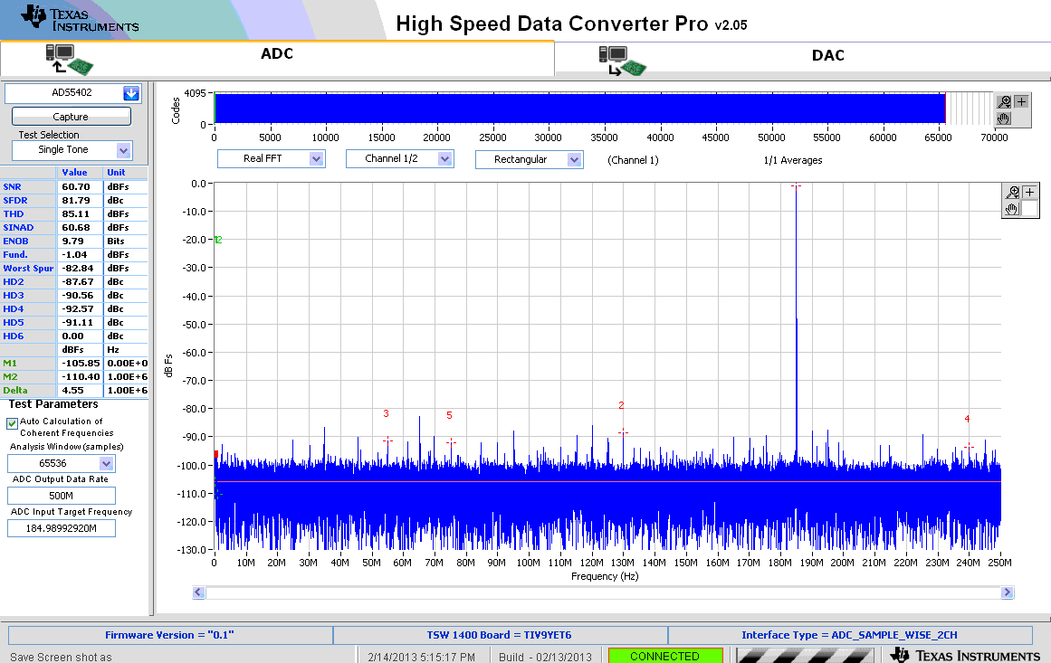
    What kind of results are you looking for?  We've been using the TSW1400 to test our ADS540x EVMs for some time now.  For each device part number (ADS5401, ADS5402, ADS5404, etc) we build a batch of EVMs to be put in stock, and each EVM is tested before stocking and the FFT plot is saved for the serial number on that EVM.  Attached is one such FFT plot for an ADS5404 EVM.    This was taken using the firmware that was installed with the version of HSDCPro shown in the plot.  

    Regards,

    Richard P.

  • I want to update this issue in case anyone has the same problems. I upgraded to Quartus II 14, and it appeared to have solved my problem for a few hours, before there were suddenly compilation issues. I spoke to Altera, and they were able to recreate the issue, but unsure of the cause. They suggested a reinstall again, or upgrade to 15. A re-installation of Quartus II 14 did not solve it, but Quartus II 15 did, and I have had no more issues since.