This thread has been locked.

If you have a related question, please click the "Ask a related question" button in the top right corner. The newly created question will be automatically linked to this question.

ADC12D1800RB not responding to input voltage

Other Parts Discussed in Thread: ADC12D1800

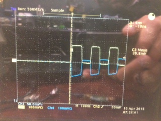
I am currently using the reference board as described in the guide. I am using a photo-detector putting out approx. 500mV into the ADC-WB-BB Balun and then into the I channel. I independently verified the detector output voltage using an o-scope.  In WaveVision 5 and I am seeing around 2,050 counts all the time even when varying the detector output. Even unplugging the detector will not affect the output. I've calibrated the ADC and I am using nonDESI for the settings. I have DC blocks installed on all four inputs (I+, I-, Q+, Q-) and I am using the internal clock. The status lights on the RB are all good.  I am using an RG174 cable from the detector to the RB as well. I do not have quick access to a function generator so I can remove the detector and check the board. I was hoping to bounce this off of someone to make sure I wasn't missing something. Any help would be appreciated. Thank you.

  • Hello Justin,

    What is the frequency of the photo-detector output? the ADC-WB-BB has a low frequency limit of 4.5MHz. Frequencies below this will be severely attenuated.

  • Its frequency can range depending on gain setting. If at 10db gain, it is 8.5MHz. 0dB is 17MHz. Since my initial post, I located a function generator and put in a 300mVp-p, 6MHz square wave (verified by o-scope) and I still get a DC line at 2050 counts. It is not a solid line and does have some noise on it (~10 counts).
  • Hi Justin,

    It sounds like the frequency is in the right range. Does your photo detector need high impedance? When you measured with the o-scope, was it connected directly with 50Ω impedance? Measured with a high impedance probe? Could you upload the scope shots of your waveforms?

    Thanks!
    Luke LaPointe
    High Speed Data Converters

  • The detector output impedance is 50 Ohm and so is the output of the function generator.  I am using a 50 Ohm cable and connecting to the 50 Ohm input of my o-scope.  Below are screen shots of the o-scope when looking at the detector with controlled DC light on it and the function generator square wave output.

  • Hello Justin,

    I would first verify that the balun (ADC-WB-BB) you are using to connect to the ADC12D1800 is working properly. I tried to recreate the condition which you describe and only noticed failures if one of the balun outputs (Vout+/Vout-) was left floating.

    I tested with the input signal below.

    Using the ADC-WB-BB the signal becomes AC coupled, but the signal switches fast enough so that there is not much droop/attenuation of the DC content. Comparing the waveform measured by an o-scope and by the ADC12D1800 shows no degradation.

    If Vout- is floating, the waveform becomes attenuated and distorted, but again the results are similar comparing the o-scope to the ADC12D1800.

    The worst case is if Vout+ is floating, which may be what you are seeing.

    I would verify that the balun is not damaged or that the connections are not loose. It would also be good to verify the signal through the balun into the o-scope and report the results back here.

    Regards,
    Luke LaPointe
    High Speed Data Converters

  • Luke,

    Below are the balun outputs (V+ top, V- bottom) when feeding in the function generator's square wave to the balun input.  I checked connections and all appear good. I also looked closely at the balun and nothing seems out of place or damaged.  If the balun is bad and killing my signal, I would expect Wave Vision 5 to report ~0 counts and not 2050. Correct? Is there something else causing the high offset? Based on the pics below, there is definitely something up with the balun but I wanted to think about the high offset as well. Can I get a balun replacement on the way?

  • Hi Justin,
    WaveVision reports ADC code on the y-axis. So for the ADC12D1800 min code is 0 while max code is 2^N-1 = 4095. If there is no signal, the converter should be sitting at mid code or 2048. Additionally since this is a differential input ADC, you will not see any DC offset unless the input signal is not balanced or has a differential offset. However, your most recent waveforms confirm my suspicion that the balun board is somehow damaged. I would verify that the passive components (C1, R1, etc) are not damaged. My guess is that C1 somehow got damaged which can be easily replaced.
    Regards,
    Luke LaPointe
    High Speed Data Converters
  • The passive components appear OK visually under a microscope. Please tell me the sizes (they look like 0402) and values of the components and I can replace them. I will have to order the components unless it is quicker to get a replacement balun from TI. We just purchased this board so I wasn't sure of the warranty options.
  • Hi Justin,

    The passive components are 0402. I've attached the BOM here:

    ADC-WB-BB_BOM.xls

    Alternatively, if you wish to return the board or get a replacement please see our return policy here:

    You may fill out the following form if you'd like a replacement:

    Regards,
    Luke LaPointe
    High Speed Data Converters

  • Luke,

    It was most efficient for me to buy a new balun board. I received it today and I still get the same outputs from V+ and V- as the previously posted pictures.  I am still feeding in the same square wave from my function generator. Any ideas?

  • Hi Justin,
    When you test on the oscilloscope can you verify that both V+ and V- are connected at the same time? Is it possible to measure with both channels displayed on the screen simultaneously?
    Thanks!
    Luke LaPointe
    High Speed Data Converters
  • Luke,

    I was finally able to get time to get that data. The first image shows the output from the function generator. The second shows the outputs from the balun when the function generator as the balun input.  V+ is yellow and V- is blue. Is this output you expect from the balun board? This is the first time I have had both balun outputs connected at one time to the o-scope.  Using the new balun, I still get a flat 2050 counts on the ADC output when using Wave Vision 5. Any ideas?

  • Justin,

    It appears that there is a common-mode fluctuation at the balun output on the order of 50mV which is not desireable, but it may be expected because pulse duration appears to be ~100ns and the lower operating frequency of the balun is ~5MHz. You may also verify that the connections to the oscilloscope were AC coupled to a termination at the scope.

    It also does appear that a differential signal is being output from the balun, so the ADC should be detecting the signal if the balun is properly connected to the ADC input. Have you looked at the spectrum yet? With that square wave input, there should be tones at 5MHz, 15MHz, 25MHz, etc....

    Have you tried inputting the square wave into both channels?

    Regards, Josh

  • Josh,

    I just verified my o-scope was not set to AC coupled. I still had it set to DC coupled for checking my photo-detector output. Good catch.  Once I changed to AC coupled, the output from the balun (still using the function generator square wave as the input) looks pretty good as shown in the first picture.  I then took the outputs of the balun from the o-scope and connected them to the inputs of the ADC as shown in the second picture.  I'm still seeing 2050 counts in the time domain plot and the FFT plot is not showing any tones, see third picture.  I moved away from the function generator and tried my detector again.  I first verified the output from the detector by using the o-scope in DC coupled mode. The detector responded as expected to varying light input.  I then put the detector output into the balun input.  I looked at the time domain plot and see a steady 2050 counts with varying light input to the detector.  I am using the I Channels and I have the V+ balun output going to the I+ input of the ADC. I have DC blocks installed as well. I am using nonDESI mode in Wave Vision 5.  Are there some setting I am missing in Wave Vision? 

  • Justin,

    The only Wavevision setting that I can think of is the channel selection drop-down box, which has all the options for selecting the right mode (DES/non-DES) and the channel. I have marked it below, though I do not have a board at my disposal to show all the options.

    Regards, Josh

  • Wave Vision recognizes the board and nonDESI selected on the drop down box you circled. That doesn't seem to help out. I'm stuck at this point and not sure where to go next. Any ideas? Do I have a bad board? Is there another I can try out? Should I contact someone about Wave Vision 5 settings?
  • Hi Justin

    Your setup should provide good results at 10 MHz. I set up an ADC12D1800RB with an ADC-WB-BB and DC-blocks, and a 5 MHz input square wave. Using nonDESI mode I was able to capture the waveform below:

    If you aren't getting a good square wave capture after everything you have verified it may be possible that the board is damaged.

    Before returning the board, please try one more thing. Re-configure the board for nonDESQ mode, 16k or 32k sample depth, and connect the output of the balun board to the DC-blocks on the Q channel inputs instead. Please try a few captures and send us the time domain screen shot of the results. If no square wave is seen then I think you should proceed with a warranty return on the ADC12D1800RB board.

    Best regards,

    Jim B

  • Hey guys,


    I was finally able to get the board functioning properly through the I and Q channels.  I hate to say it, but it was my fault on the way I was using my function generator.  The function generator was bursting the square wave and my o-scope was displaying just fine due to my trigger settings but the ADC board didn't like it. Once I discovered this and turned it off, the square wave popped right up.  Thanks for all of the troubleshooting help.

    I have a new question regarding the Wave Vision software.  Your screen capture on the last post looks just like mine (version #, available toolbars, etc...).  I would like to record the ASCII data from the plot and the user manual says there should be a button for that.  My version doesn't seem to have that functionality, only to import ASCII.  I can save the plot and profile and then open it in Wave Vision, but I would like to import the data for further work in another program.  Any ideas?

    Thanks again for the support. I've been kicking myself on this one.


    Justin

  • Justin,

    Glad you found the issue!

    The ASCII export button is in the Channels tab on the left side of the window after you have data in the plot. Note that this will export the kind of data showing in the plot, either time domain or frequency domain magnitude.

    Regards, Josh