This thread has been locked.

If you have a related question, please click the "Ask a related question" button in the top right corner. The newly created question will be automatically linked to this question.

ADC08D1520RB does not respond to signal fed in

Other Parts Discussed in Thread: ADC08D1520RB

Description:

ADC08D1520RB is unable to digitize the sine wave fed in and only noise is observed on WaveVision. 

The sine signal frequency is 100MHz and level is -1dBm and -2dBm.

over_range LED flash is observed. 

Questions: 

1. how to solve it? 

2. Does WaveVision and FPGA image of ADC08D1520RB change recently? 

  • Hi Bridget

    Is the input signal a continuous sine-wave?

    Which balun board are you using to convert the signal from the generator to differential?

    Are the DC-Blocks utilized in between the balun board outputs and board inputs?

    Which inputs (I+/- or Q+/-) is the signal connected to?

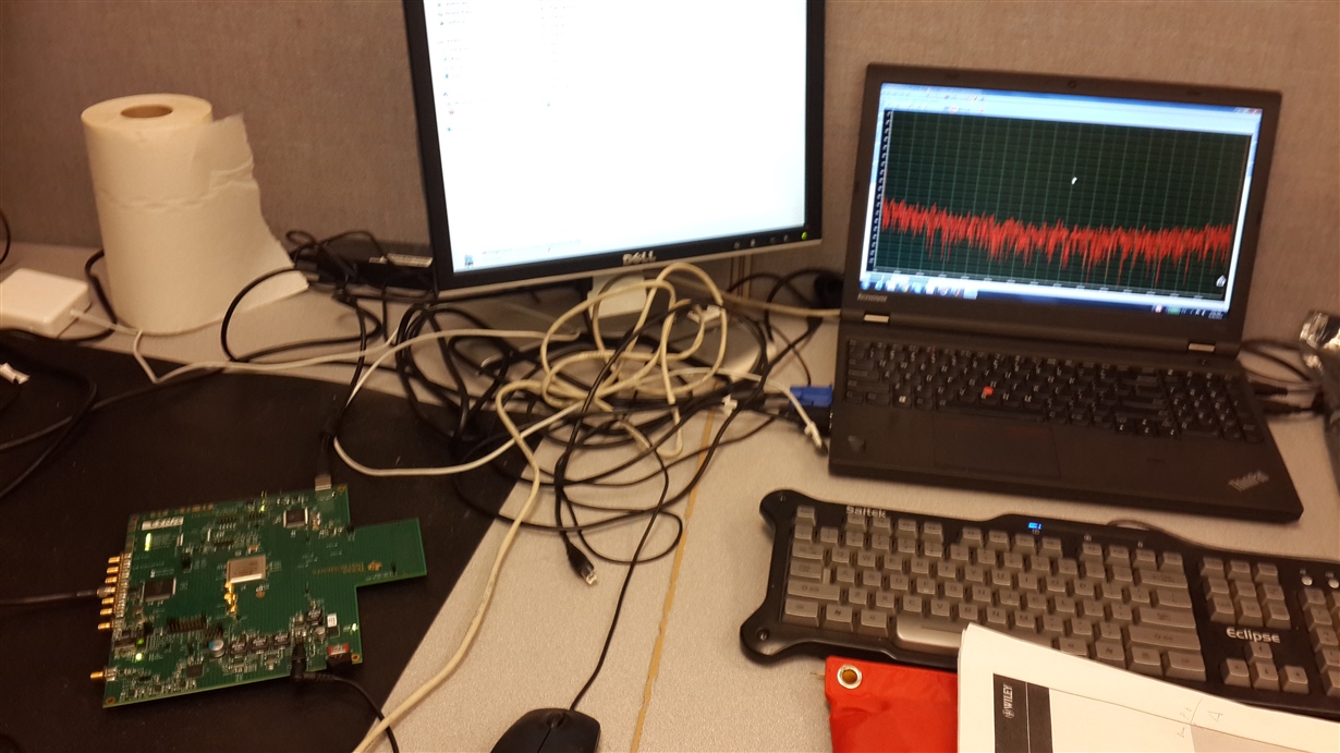
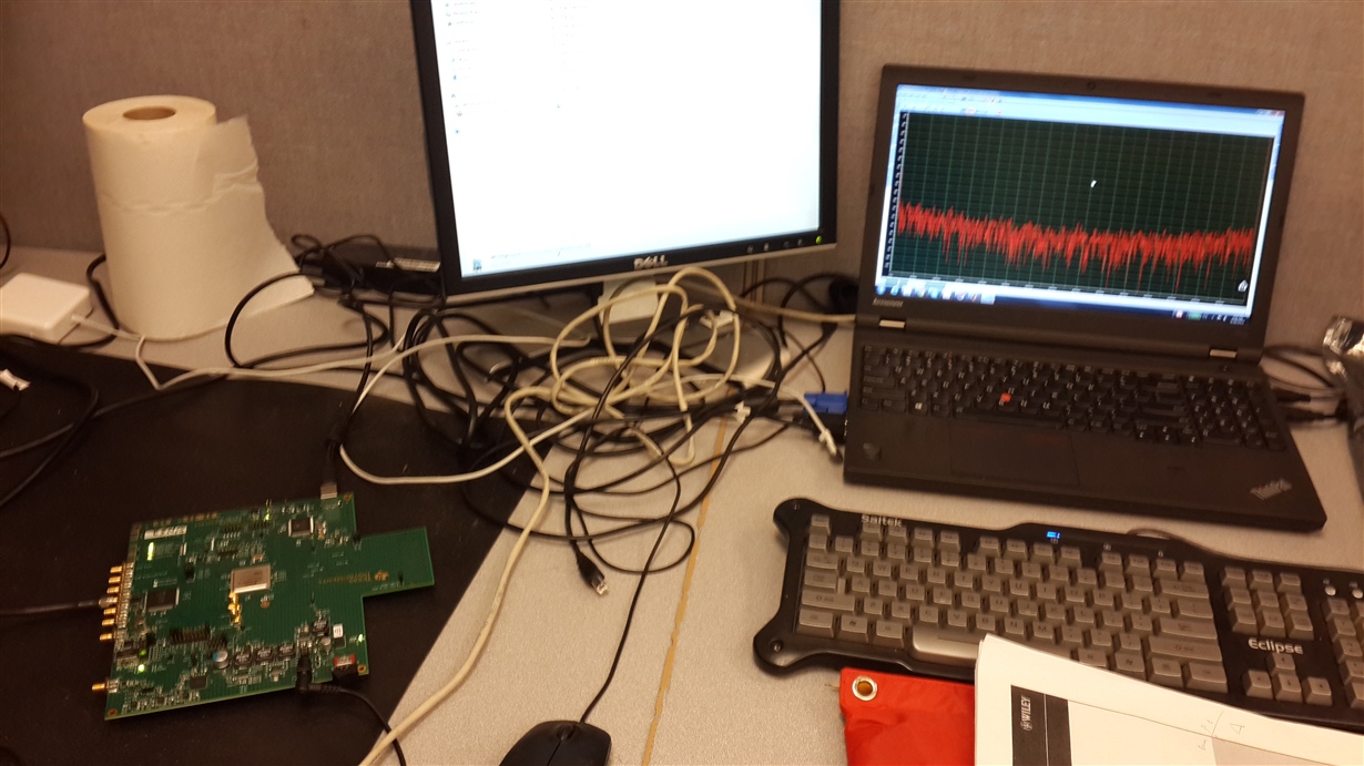
    Can you send a picture of your setup, along with a snapshot of the Wavevision GUI showing the time domain waveform and board configuration (input and sampling mode and capture depth are the most important)?

    Best regards,

    Jim B

  • Hi Jim, 

    Thank you for your reply. Please find the answers as following. 

    Is the input signal a continuous sine-wave?

    Yes

    Which balun board are you using to convert the signal from the generator to differential?

    ADC-WB-BB  (I used it but only observe noise. the photo was taken while the board does not connecting with the balun)

    Are the DC-Blocks utilized in between the balun board outputs and board inputs?

    No

    Which inputs (I+/- or Q+/-) is the signal connected to?

    Tried both of I + and I- and only noise is observed.

    Can you send a picture of your setup, along with a snapshot of the Wavevision GUI showing the time domain waveform and board configuration (input and sampling mode and capture depth are the most important)?

    Best regards,

    Jim B

  • Hi Bridget

    Thanks for the additional information. Please note that the analog inputs are internally biased to the ADC Vcm (common mode input voltage). Therefore any external signals must be connected using DC-blocks to prevent the external signal from pulling the input voltage below the proper common mode voltage.

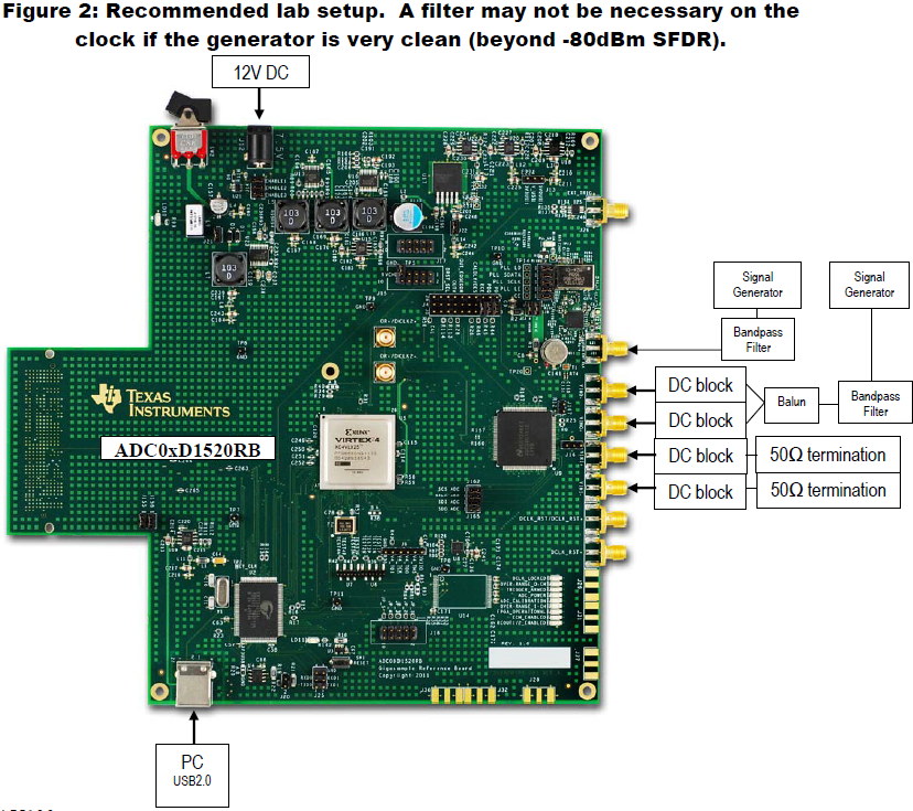
    In addition, the inputs must be driven with a differential signal applied at V_IN+ and V_IN-. The supplied balun boards and DC-blocks should be used to adapt the single ended output of your signal generator to the differential inputs as shown in Figure 2 of the ADC08D1520RB user guide, also copied here:

    Please try connected your signals as shown in the diagram, including using the DC-blocks and let me know if you are able to get the expected results.

    Best regards,

    Jim B

  • Thank you very much for your reply, Jim. 

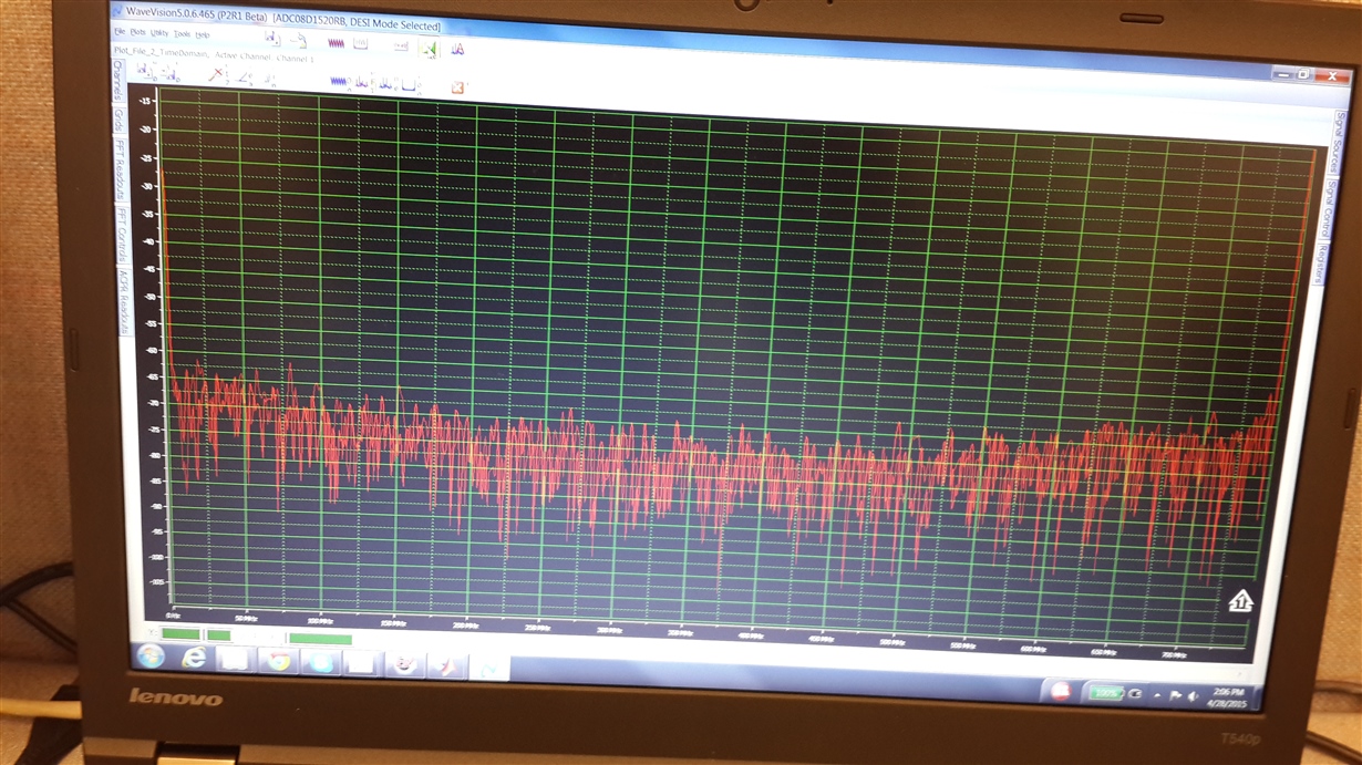
    1. The common mode of the board might cause harmonics which is up to the input signal level, but it does not affect the board to digitize the input sign. In the attached the photo, only noise is digitized as showing in the following photo. 
    2. The differential signal will help to provides more precise signal level. If only on of v_in+ an v_in- is fed a sine wave, the board at least be able to return a peak of the sine in frequency domain. However, the board only returns noise. 
    3.I only have the board with me now and that picture I just photoed is to show  basic connection. When i was doing testing, I have all those required pieces suggested by the user guide, but WaveVision only returns noise. Thus, I suspect the problem is caused by the board itself. Adding dc block, balun, and even a filter between signal generator and the board does not do any good for observing a peak of the input sine wave in wavevision. 
    Thanks. 
    -Bridget
  • Hi Bridget

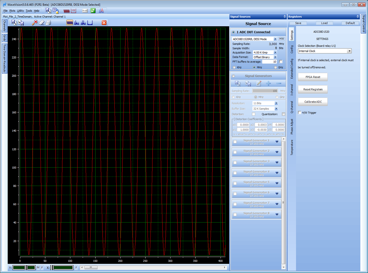
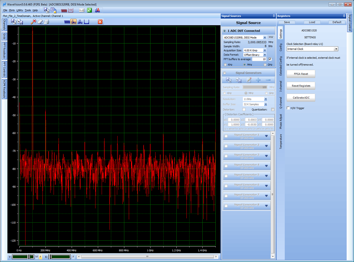
    For that mode and with a 100 MHz input at -1dBm applied to the balun board this is what the time and frequency domain plots should look like:

    Time

    Frequency

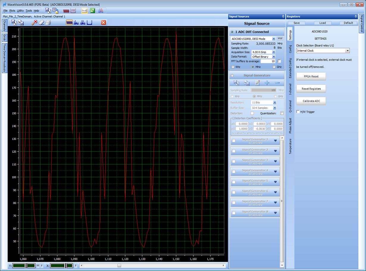
    I also tried applying a SE signal directly connected to VIN- with no DC block. Here is what that looks like, the distortion caused by driving the input in that manner is evident, but there is some resemblance to a sine wave.

    Please confirm your signal generator output using an oscilloscope. If the signal is as expected and you are still unable to get the expected capture into the ADC08D1520RB please proceed with a warranty return.

    Best regards,

    Jim B

  • Thank you very much for your reply, Jim. 

    The signal output is confirmed by an oscilloscope. Thank you!

    -Bridget