This thread has been locked.

If you have a related question, please click the "Ask a related question" button in the top right corner. The newly created question will be automatically linked to this question.

questions on ADS5407EVM

Other Parts Discussed in Thread: ADS5407, ADS5402

Hello,

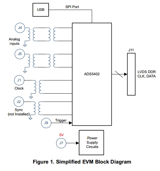
We are using ADS5407EVM. As I learn from the user manual, each analog input is supplied to the EVM through dual transformers, but the clock is through a single transformer. Please see the attached picture.

The user manual says that "A dual transformer input circuit is used for better phase and amplitude balance of the input signal than would typically be produced

by a single transformer input circuit." Our questions is why? We have used a lot of other ADCs and we use one transfomer other than two, and that is OK. Do we have to use dual transfomers with ADS5407's analog input?

Thanks a lot!

Best Regards,

Sam

  • Hi,

    As stated in the User Guide, the back to back transformers often result in the most balanced conversion of a single ended input to differential.    We use many different brands and part numbers for the transformers or baluns used on our EVMs, depending on the expected range of input frequency for that EVM.   The datasheets for these transformers often specify output imbalance, but the actual output imbalance is often better in the middle of the device's bandwidth and worse at high or low frequency input, and the balance might be specified with differential input to the transformer and we are using single ended input.    Plus, the transformer will have some package parasitics of its own that is usually not specified.  We have done some circuit simulations where we assume a few pF of pin to pin parasitic capacitance in the transformer package, and we can see that single ended to differential conversion results in some amplitude imbalance at the secondary with the assumptions we made.  The second transformer in the chain is *not* doing single ended to differential conversion, so its signal at the primary is already mostly balanced and the secondary is more balanced yet.  In a way it is like the first transformer gets us most of the way to differential and the second transformer gets us more of the way there.

    If there is an imbalance of phase or an imbalance of amplitude in a differential signal, then the result of that imbalance is a ripple on the common mode.  I am attaching a file that illustrates an exaggerated sketch of the concept.    Many of our high speed ADCs have a range of VCM voltage that the ADC can tolerate, but that specificaiton is for a DC level of the VCM.  Our ADCs don't like to see an AC component to the VCM.   Ripple on the VCM will sometimes adversly affect the SFDR of the ADC.

    Now, every brand of transformer is different, and every customer's input frequency bandwidth and expectations on SFDR performace is different, so back to back transformers may not be worth the extra cost in every case.   On some of our 16 bit ADCs with very good SFDR performance, a little degradation of the SFDR becomes more noticeable because the noise floor and input harmonics are so far down already.  On a device like the ADS5402 which is only 12 bit and at a higher sample rate, the normal noise floor of the device is already higher than most of our devices and some input signal imbalance may not result in anything noticeable at all.  But we make the EVM to show the datasheet performance of the ADC  itself and so we try to make the EVM itself be not a limiting facter in the evaluation of the ADC on the EVM.

    The clock input does not care about signal balance or harmonic content at all, as long as the rising edge of the clock is 'seen' at the same point in the clock waveform for every cycle of the clock.  I see that there is now a duplicate posting since I took a while to repond to this one, so I will delete that duplicate posting.transformer balance.ppt

    Regards,

    Richard P.