This thread has been locked.

If you have a related question, please click the "Ask a related question" button in the top right corner. The newly created question will be automatically linked to this question.

TSW1400EVN How To Develop with TI Sotfware ?

Other Parts Discussed in Thread: AFE5809, AFE5809EVM, AFE5851EVM, AFE5851

Hello,

Our team would use TSW1400EVM with AFE5809 to implement our system.

And I have some questions in how to develop our system easier.

As we know, TSW1400EVM has two ways to write code in it.

One is use TI software to write the firmware. The other is change some registers to use the JTAG.

If  we use TI software and change our FPGA code to the firmware form, so we can write the code to the board.

But how me know or see the code we writed is good to go ? (How to use TI software to see the result ?)

Because if we use JTAG with Quartus to develop the FPGA code then we would see the I/O, the chip...etc.

And if we use JTAG with Quartus, we would see lots of high and low voltage.

But I afraid that we might not figure out the data is right or not.

So do you have any suggestion to this situation ?

Kind regards,

Jerry

  • Jerry,

    What type of changes do you plan on making? Will these changes be tested with an AFE5809EVM plugged into a TSW1400EVM and using HSDC Pro? If the changes are minor, you can compile your design in Quartus, then convert the .sof file to a .rbf file and load the new firmware using HSDC Pro. If the changes are major, I would suggest modifying the TSW1400EVM so that you can use the JTAG connector, then load the firmware with a USB Blaster cable and use Quartus Signal Tap to monitor signals and data inside the FPGA. If you do this modification, you still may be able to operate HSDC Pro Software, but you would have to load your new .sof file through a USB Blaster cable using Quartus since the interface between the FPGA and HSDC Pro that loads firmware will be disconnected.

    Regards,

    Jim

  • So does it means if we modifyed the TSW1400EVM 

    (Remove: R61 R62 R63 R64

    Install: R55 R57 R58 R59 R60 R129

    All resistors are 0 Ω, except R55 which is a 1 kΩ.)

    the USB mini port is still work ? (Does USB mini port still connect to the computer,it means can it transport some data to the computer?)

    We want to use the TSW1400EVM  to connect the  AFE5809EVM and get the ADC data,

    and then we also use TSW1400EVM to process the data and back to the computer.

    So according to the above function, I have already get the source code of TSW1400EVM, and begin to study this.

    But I know the HSDC Pro also transport some parameters to the board. (like the "Additional Device Parameters.  ADC Sampling Rate ...etc")

    If we modifyed the TSW1400EVM, can we still use the HSDC Pro to transport this setting or we have to do this in the FPGA code?

  • Jhin,

    If you do the modifications you mentioned, HSDC Pro will still be able capture data and send patterns as long as the firmware supporting these functions is unchanged, but it will not be able to configure the FPGA. You will have to do this manually using an USB Blaster pod connected to JTAG connector J13 and the Quartus programming tool.

    Regards,

    Jim  

  • Jim,

    Thanks for your above answer.

    And i try to download the verilog source code which has been changed to firmware(.rbf) with HSDC Pro, and use HSDC Pro to capture.

    But it has "Frame clock error in Read DDR to file" error.

    Is the source code named "TSW1400_ADC_Firmware_12_12_14" work in TSW1400EVM with the AFE5809EVM or 5808?

    Or are there some parameters should be set in the beginning?

    My Questions :

    1. If the source code is not good to work in our condition, how to find the right source code?
    2. if the source code is good to work, then what is the reason to show the error?
    3. And it should be some parameters to be set in the beginning, what is the part of parameters in the verilog source code?

    I really appreciate your help.

  • Jhin,

    In the defines.vh module, you will need to edit the following parameters: Change the Interface_ID from 8'd16 to 8'd10, comment out define SAMPLEWISE_DDR then uncomment the define BITWISE_DDR mode you are using.

    Regards,

    Jim

    `define INTERFACE_ID    8'd10


    //define     SAMPLEWISE_DDR
    //`define   BYTEWISE_DDR
    //`define   BITWISE_DDR_2W_12B
    //`define   BITWISE_DDR_2W_14B

    //`define   BITWISE_DDR_2W_16B

    //`define   BITWISE_DDR_4W
    //`define   BITWISE_DDR_1W

    //`define   BITWISE_DDR_1W_10B

    //`define   BITWISE_DDR_1W_12B

    //`define   BITWISE_DDR_1W_14B

    //`define   BITWISE_DDR_1W_16B

  • I have changed the INTERFACE_ID to 8'd10, and let SAMPLEWISE_DDR commented.

    And let other BITWISE_DDR define uncommented one by one.

    (like this)

    //`define SAMPLEWISE_DDR
    //`define BYTEWISE_DDR

    `define BITWISE_DDR_2W_12B

    //`define BITWISE_DDR_2W_14B
    //`define BITWISE_DDR_2W_16B
    //`define BITWISE_DDR_4W

    //`define BITWISE_DDR_1W

    //`define BITWISE_DDR_1W_10B
    //`define BITWISE_DDR_1W_12B
    //`define BITWISE_DDR_1W_14B
    //`define BITWISE_DDR_1W_16B

    And all of these have error.

    BITWISE_DDR_2W_12B, BITWISE_DDR_2W_14B, BITWISE_DDR_4W, BITWISE_DDR_1W_10B, BITWISE_DDR_1W_12B, BITWISE_DDR_1W_14B, BITWISE_DDR_1W_16B are "Frame clock error in Read DDR to file".

    But the BITWISE_DDR_2W_16B, BITWISE_DDR_1W are "read DDR to File TIMED_OUT_ERROR Time Out error".

    I have no idea what is going on.

  • TSW1400_REVAMP_BETA_RELEASE_DEC10_2012.zipJhin,

    You may have an older version of firmware. Please try with version attached.

    Regards,

    JIm

  • Thanks for your help.
    Now I can download the new version verilog source code (change to firmware) to the EVM board.
    And run it with HSDC Pro for test. It can work like original firmware for the TSW1400EVM.


    But now we change our ADC form AFE5809EVM to AFE5851EVM, and have some problems.
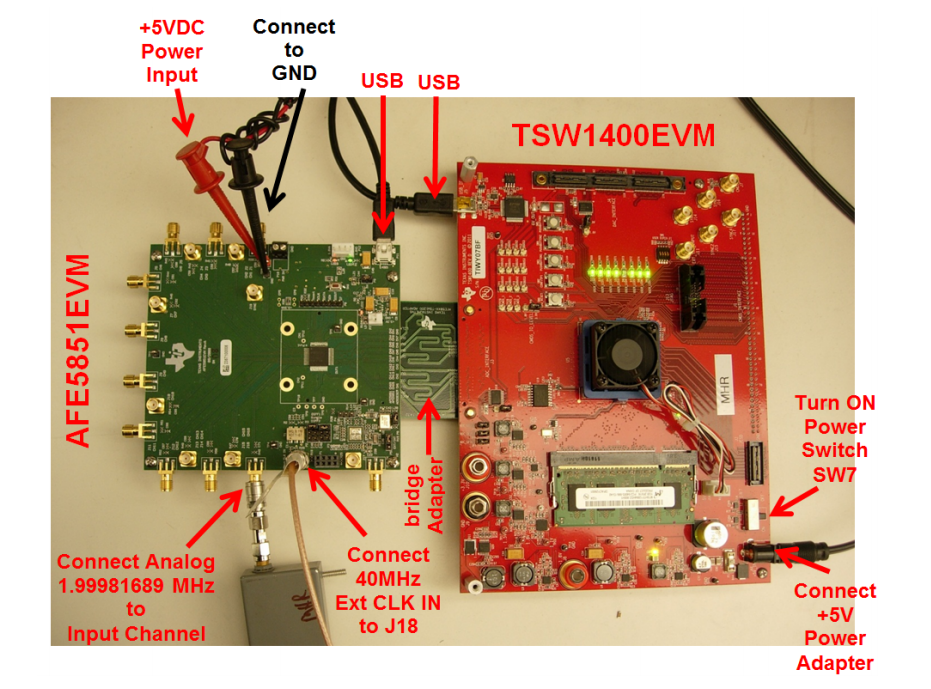
    We follow the AFE5851EVM user guides.
    But when we use the HSDC Pro to capture test data, it have "read DDR to File TIMED_OUT_ERROR Time Out error" error.

    Some differences:

    Hardware setup:

    In the user guides, it has a bridge adapter between the AFE5851EVM and TSW1400EVM.

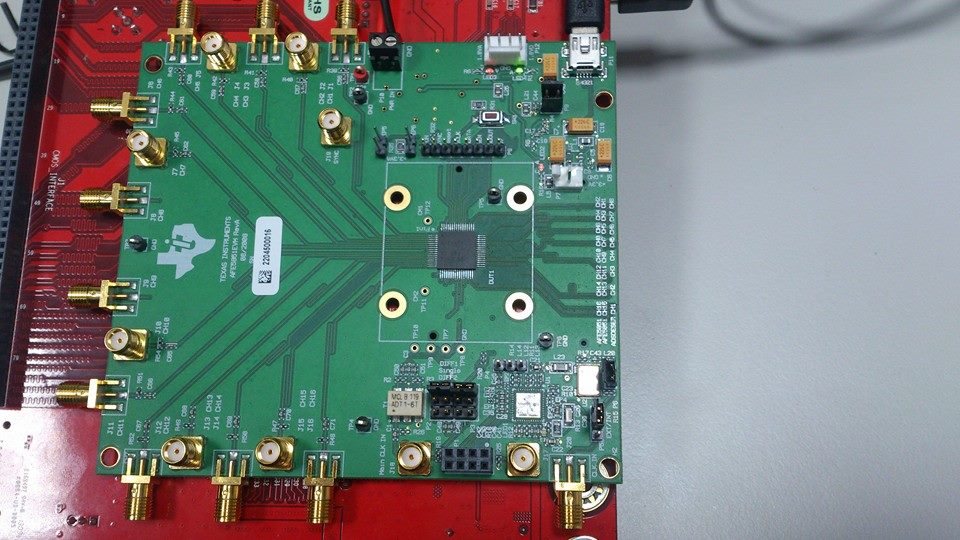
    We have buy it, but haven't got it yet. So for now our hardware setup is like the second picture. 


    And the ADC power is 5VDC with 0.5 A.

    Ext CLK IN is 40MHz and 13dBm(high 2.825V, low 0V)

    My Questions :  1. Is bridge adapter necessary or it just to connect?

                                2. Does the hardware setup have any problem?

    Software setup :

    In the user guides, ADC5851 need to 

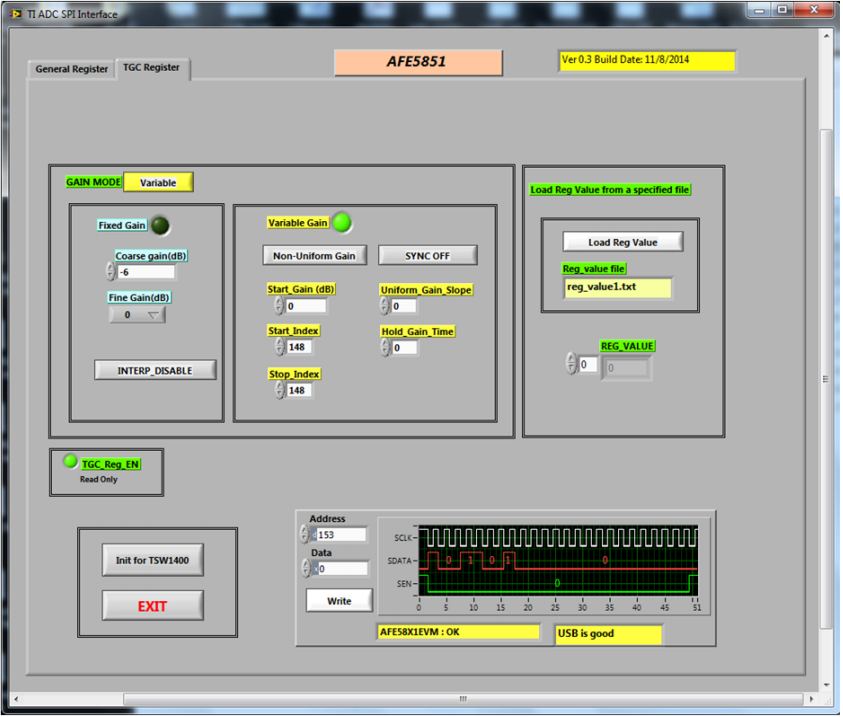
    init for TSW1400  ->  Select TAB "TGC Register" ->  press "Variable" toggle button ->  enter 30 in the "Coarse Gain(dB)" field, then press "Write" button.

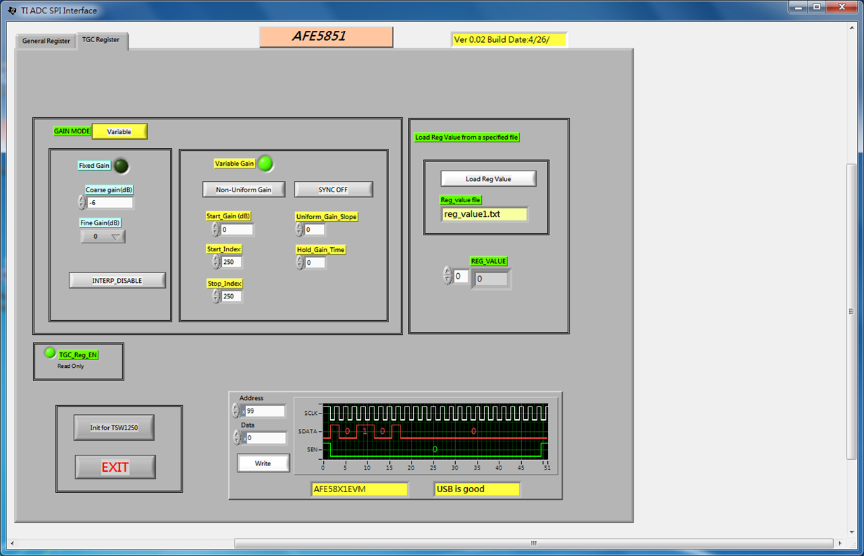
    But the AFE5851EVM software in the TI web is like below picture. It does have "init for TSW1400", it just have"init for TSW1250".

    So the Software setup is like

    init for TSW1250  ->  Select TAB "TGC Register" ->  press "Variable" toggle button ->  enter 30 in the "Coarse Gain(dB)" field, then press "Write" button.

    My Questions :

    1. Is the AFE5851 software version is right or not?

    2. Is that we don't let the ADC to init for TSW1400 so that it have time out error?


    p.s

    In HSDC Pro setting, just choose AFE5851_12X firmware and set the ADC output data rate to 20MHz, and set the ADC input frequency to 2MHz.