This thread has been locked.

If you have a related question, please click the "Ask a related question" button in the top right corner. The newly created question will be automatically linked to this question.

ADC12D1600RF Calibration Issue

Other Parts Discussed in Thread: ADC12D1600RF

Hello,

We use ADC12D1600RF interfaced with Virtex-6 FPGA in our high-speed EMI measurement system. There have been a number of boards with this ADC that we have used without issues. However, we have disabled on-command ADC calibration due to the uncertainty in the ADC behaviour after calibration. As sometimes it becomes imperative to use calibration to compensate other issues like spurs at fs/2 and aliasing spurs, I need to find a solution for this.

Steps followed to Calibrate the ADC :

1) Prior to every measurement, the ADC is calibrated.

2) Most of the times the calibration is successful, however some other times it is not.

3) I have tried using both available methods to calibrate the ADC - a) Pulling the CAL Pin low and then high (with the Bit 15 of CFG Reg 0 always set to low) or b) Setting the Bit 15 of configuration register 0 low and then high (with the CAL pin always low). In both the cases the low and high times are much higher than what has been specified in the data sheet of the ADC.

What is observed :

8 out of 10 times the calibration seems to have worked fine. The spectrum of the ADC signal in this case is as shown below (although there is a large aliasing spur at fs/4 + fin):

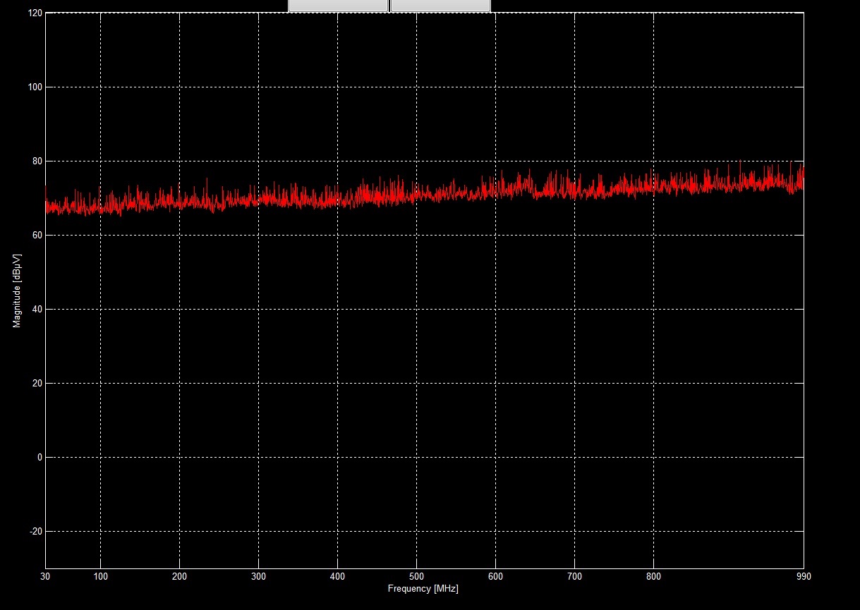
2 out of 10 times the ADC goes crazy. The below figures illustrate the spectrum of the ADC signal when this happens. You could see the spectrum is completely out of order with a very high noise floor and some other manifestations like bumps, wrong signal levels, non-smooth noise floor etc.


After the ADC goes crazy, on running subsequent measurements (which also does calibration each time), the ADC recovers sometimes but some other times not. For a test system like ours this behaviour is not at all accepted. So, it would be nice if someone could help me out in addressing/debugging this issue. May be there's something wrong that I might be doing.

FYI, the ADC is configured as follows :

1) Sampling frequency is 2.6 GSPS

2) ADC is configured in 1:4 Demux DES Mode with DDR

3) The configuration register values is as given below : (I have also tried only setting Registers 0h and Eh while not modifying/writing into other register locations. But, this did not seem to have any effect)

Looking forward to your help.

Thanks,

Prashanth

  • Hi Prashanth,

    Can you please confirm the sampling rate is 2.6 GSPS not MSPS. We have not seen this issue before, there might be a possibility that your FPGA is not properly capturing the data after calibration. Here is what I would like you to try, when the ADC is not calibrating properly try the test pattern mode and try you see if you are getting the expected pattern from the ADCs outputs.

    Regards,
    Neeraj Gill
  • Hi Neeraj,

    Thanks for the quick reply !! Yes it's 2.6 GSPS (not MSPS)...

    Also, the ADC is configured in 1:4 Demux DES mode with DDR and the DDR Data-to-DCLK phase relationship is 0 degrees (i.e. Bit 14 of Reg 0 is set to 0).

    This is the method we use to capture the ADC data :

    1) The DCLK of the ADC is fed into a Mixed Mode Clock Manager to generate a buffered in phase clock at the same rate as DCLK.
    2) This buffered clock is then used to sample the DDR data which are then aligned and processed further.

    Do you see any issues in this method ? Does the phase of the DCLK w.r.t DDR Data change after/during calibration ? What could be other possible reasons for the FPGA not capturing the data (which might help me in debugging the issue) ?

    I will also try the test pattern mode in the meanwhile..


    Thanks,
    Prashanth

  • UPDATE: I set the test mode on and here's what I observed :

    1) After the ADC went crazy, the test data that was received from the ADC was completely out of order. 

    2) Even though they were out of order, 95% of the data received was among of those specified in the test pattern sequence (000h, 004, 008h, 010h, fffh, ffbh, ff7h and fefh) . The rest 5% of the data were junk (eg: 00ch, cffh, 0ffh etc).

    3) After the ADC recovered (powered on/off the system a couple of times), the data that was read perfectly matched the test sequence. There were no junk data received at all.

    Even with calibration (on-command) turned off all the time I see this issue happening with this ADC. What do you suggest me to do next ? 

    Thanks,
    Prashanth

  • Hi Prashanth,

    In test pattern mode, the ADC is disengaged and a test pattern generator is connected to the outputs of the ADCs. As you mentioned you are getting junk data even in TEST pattern mode. It means there is a problem with your data capture process.

    Can you disable mixed mode clock generator and try to do a capture with using the DCLK without mixed mode clock generator. Also trying changing the phase of DCLK and data from 0 degree to 90 degree and see if it makes any difference.

    Check the supply voltage(VA, VTC,VE,VDR) for the ADC and make sure it is 1.9V . Also make sure the amplitude of clock signal is within recommended amplitude.

    Regards,
    Neeraj Gill
  • Hi Neeraj,

    The reason I was getting junk data/out of order data in test pattern mode was due to an issue in my debug code. Now that is solved and I always get the correct sequence in test pattern mode (even after the ADC goes crazy). Also, I checked the voltages and they are all fine. I read out the register values too and they were all as expected.

    I have a couple of other questions :

    1) During run-time we change the sampling frequency (i.e. ADC clock). Does this affect the ADC in anyway ? Is there something that needs to be done (like reset ADC, set register values again or perform calibration) every time the sampling frequency is changed ? 

    2) Does the power consumption of the ADC change while it is calibrating ? I couldn't find any information about this in the manual.

    FYI, we have two ADCs working in Master-Slave configuration. The master provides the reference clock to the slave and hence the Autosync register values (address Eh) have been set as 0x0001 (master) and 0x0007(slave). The rest of the register values are similar for both ADCs.

    Thanks,

    Prashanth

  • Hi Prashanth,

    1. If you are changing the sampling frequency I would recommend doing the calibration at highest sampling frequency.

    2. The power consumption of ADC should remain the same while it is calibrating.

    Regards,
    Neeraj Gill
  • Hi Neeraj,


    Thanks once again for your continued assistance !!

    In the last few days I have been working on this issue and here are a few things that I uncovered :

    1) Instead of master-slave configuration, I configured both ADCs as master for debug purposes and I wrote exactly similar register values into both ADCs so as to compare the behaviour of the two.
    2) On debugging, I found that the on-command calibration fails only for ADC1 (very consistently). However, ADC2's calibration NEVER failed.
    3) I also read the calibration register (Addr : 5h) 240 times of both ADCs and compared. I see that the values of the two ADCs are completely different.
    4) Then, I completely disabled on-command calibration only for ADC1, but wrote the calibration register values read from ADC2 into ADC1 (I was periodically calibrating ADC2 every 10 s and then was writing cal values read from ADC2 into ADC1 every time). To my surprise, the ADC1 never went crazy after this (tested for at least a couple of hours).

    So, my questions are :

    1) Why is there a huge difference in the calibration register values even though both ADCs are configured in the same way and are also operating under similar conditions ?
    2) What do the 240 calibration register values really mean or correspond to ? Also, is there any specific range within which each of the cal values should lie ? I couldn't find this info in the manual.
    3) Given that writing calibration register values of ADC2 into ADC1 is not causing failure of ADC1, I think it is safe to conclude that on-command calibration for ADC1 is failing. Is there any reason why you think this might happen ?

    Update : I disabled on-command calibration for ADC2 and enabled calibration for ADC1. I then wrote the calibration values from ADC1 into ADC2, and as expected ADC2 also started behaving crazy. This further supports our conclusion that ADC1 calibration is failing.

    Regards,
    Prashanth

  • Hi Prashanth,

    Have you tested multiple boards? if yes are you seeing this issue on other boards or this is the only board that is having issues?

    I think at this point it would be best to return the ADC chip for further analysis. Here is the link to return it.

    http://www.ti.com/lsds/ti/quality/resources/customer_returns.page

    Answering your question.

    1. All the ADCs will have different internal mismatches/performance, the calibration value for one ADC will be different than the other ADCs.

    2. All the 240 values are different coefficients calculated by the ADCs to compensate for internal mismatches etc and to improve the performance of the ADCs to desired levels.

    3. I don't know why the calibration on the ADC1 is failing. As I said before I have never seen this issue before. I think at this point it is best to return the ADC for further verification.

    Regards,

    Neeraj Gill


  • Hi Neeraj,

    We have seen this issue in multiple boards (5-10%). So, it's not a one off case and hence returning the ADCs are out of the question.

    The only solution I see is to find the root cause of this issue. I guess knowing what each calibration value means or corresponds to might be a good starting point. Is there any information available regarding this (including the range of each calibration coefficient) ?

    Additionally, while I was checking the schematic recently, I found that the CalDly pin of both ADCs are floating (no connection). TI recommends to either pull this pin high or to ground. Can the floating CalDly pin cause the issue that we are facing or is it completely irrelevant ?

    Regards,
    Prashanth
  • Hi Prashanth,

    I don't think I can share the information regarding the calibration coefficients.

    Yes, floating Caldly pin could be the cause of this issue. Please follow instruction section 5.3 from the datasheet. Please let me know if this solves your issue.

    Regards,
    Neeraj Gill