This thread has been locked.

If you have a related question, please click the "Ask a related question" button in the top right corner. The newly created question will be automatically linked to this question.

ADS850 acquisition time position

Other Parts Discussed in Thread: ADS850

Hello!

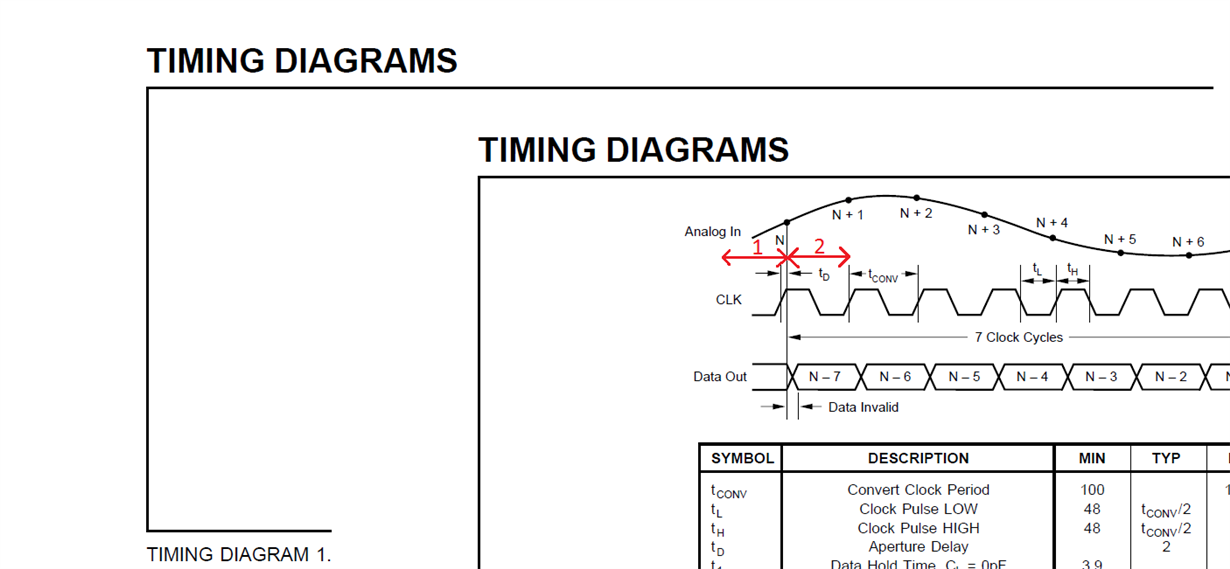
I use ADS850 in our design. I saw timing diagram 1 in ADS850 datasheet. I attached a picture from datasheet. What kind of time region (1 or 2) suggest N sample? How much time needs to acquire input voltage and convert to N sample and where this acquisition time locate on the time diagram?

With best regards, Maxim Galkin.

  • Hi,

    In that diagram, sample N is associated with the rising edge of the sample clock that just precedes the sample by the aperture delay, shown as Td.    After that sample is 'caught' it will then be another 7 clock cycles before that conversion is complete and the sample N is present at the output.

    The ADC will start with a track-and-hold circuit on the front, and during the time that the clock is low the track-and-hold circuits allows the input voltage to be present on a sampling capacitor.  When the clock goes high, a switch is opened that isolates the track-and-hold from the input voltage and the voltage that was present on the input pin is 'held' on that sampling cap so that the conversion process can begin.    Aperture delay is the time from the rising edge of the sample clock to the point in time where that input voltage is effectively held on that sampling cap.

    After that, the process begins of converting the voltage caught by the track-and-hold into a digital code.  This is a pipelined data converter, such that with each clock edge the sample is resolved into more bits of resolution and it takes t clock cycles to complete the conversion and present sample N at the output.  But it *is* a pipeline, such that while sample N is being converted in the next clock cycle after it was sampled, the track-and-hold has moved on to catch sample N+1 and start that sample into the pipeline.   So at a one time, there are 7 samples being converted throughout the pipeline.

    The time Tconv is the shorted amount of time that the device needs for each stage of the pipeline to do its job, so that sets the max sample frequency.

    Regards,

    Richard P.

  • Hi,
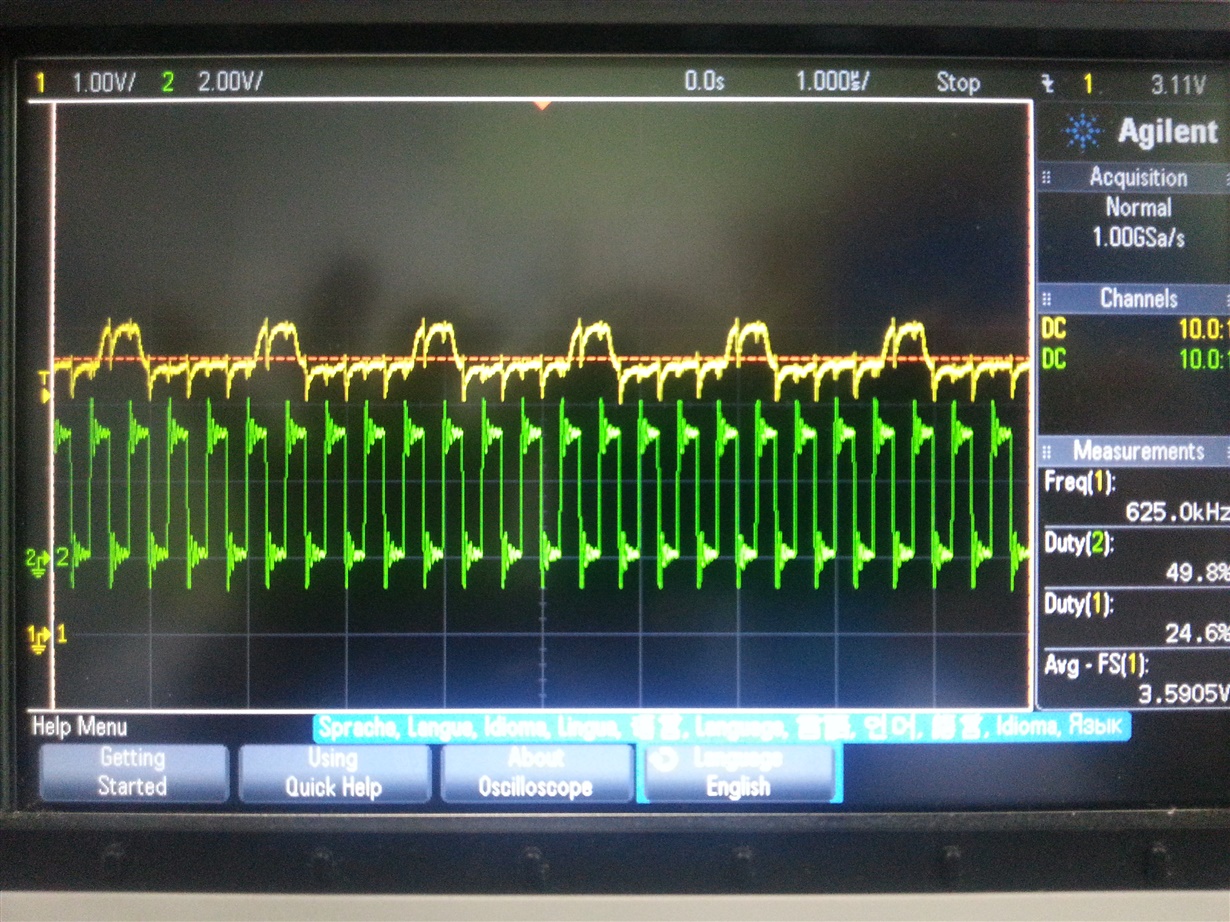
    Thanks for fast reply. I attached a picture from oscilloscope. Yellow signal is a analog signal from ADC IN+ pin. Green signal is a clock. I saw an exponential pulses when the clock goes low. This is working of S/H scheme. I understand you that acquisition time locate in zone 2 between falling and rising edges of clock signal.

    Regards,
    Maxim G.