This thread has been locked.

If you have a related question, please click the "Ask a related question" button in the top right corner. The newly created question will be automatically linked to this question.

DAC34H84 Inconsistent Behavior?

Other Parts Discussed in Thread: DAC34H84

Hello all,

I've had my fair share of troubles with this DAC in the past, and have decided to give it another go. I am using a TSW1400 to read a memory file which is then synthesized by the DAC. However, it seems *some* signals are properly synthesized, while others are not, and I'm not sure why. Here is an example of this:

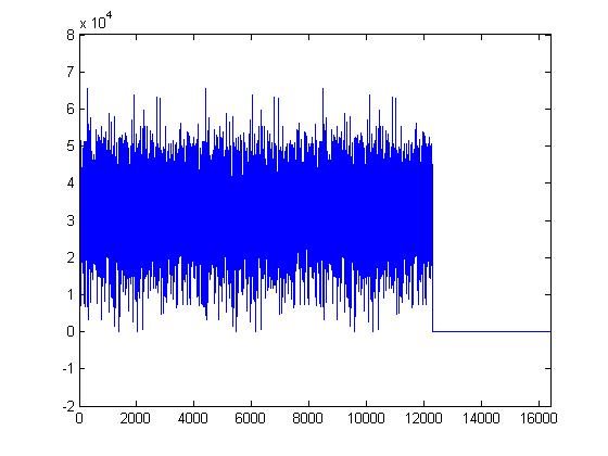
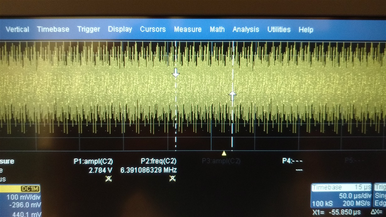
As you can see, with the second signal, my guard band is not being synthesized. I have the clock going to a counter (with no reset), and the memory is simply cycled through.I wonder why this is not being properly synthesized by the DAC, when the 'volcano' signal is? Everything else in the setup is exactly the same.

  • Nicholai,

    Since the DAC signal got chopped off around 32k (2^15) of amplitude, you will need to double check your input signal to see if it matches two's complement or offset binary format.

    I am assuming this is a triangular waveform.

    -Kang

  • Kang, the cutoff on the first signal is a red herring- it was designed to only go up to about 2^15. The first picture is a MATLAB plot of the ideal output. It is not a triangle, but rather this 'volcano' like shape. The DAC does a good job synthesizing it.

    My issue is the second signal (pictures three and four). The only difference in these setups is a different hex initialization file. In picture three, you can see there is a guard band. However, for some reason, the guard band is not synthesized in picture four. Admittedly, this signal is harder to diagnose due to its more complex nature, but the guard band would stand out clearly if it were correctly synthesized.

    Thank you for your time, Kang, it is appreciated.
  • Kang,

    I have more information for you, perhaps you can lend insight. I recreated a new OFDM signal, with a lower rolloff point. I synthesized this same signal using both an AWG and the DAC34H84.  However, it seems the DAC output is very ugly compared to the AWG. Here are two spectrum analyzer pictures of the two. I think if I could figure out what is going on with this signal it would solve my problem. Here is the AWG spectrum, looking how it is supposed to:

    Here is the DAC spectrum:

  • Nicholai,

    My understanding the DAC setup is already working and you are trying to generate your own signal for playback. 

    For the zeros, you may need to actually add zeros at the end of the csv file for the TSW1400/HSDC PRO to playback properly. The TSW1400 plays back the .csv file in a loop back mode. I don't see a reason why it won't playback zeros.

    also, instead of using zeros for your OFDM setup, perhaps you may want to add some cyclic prefix in the end (basically a portion of the repeated signal from the last frame) to see if the TSW1400 can properly playback. This may also help you with possible channel estimation/multipath compensation. 

    You may use our TSW1400 Signal Generators to generate signals such as LTE signal, which is a type of OFDM signal with certain pulse shaping. This may help you understand if there are other things that need to be improved in terms of signal setup. The generator can be found on the TI web.

    Unforunately since this is a signal generation type of question, our support for this is very limit. 

    -Kang

  • Nicholai,

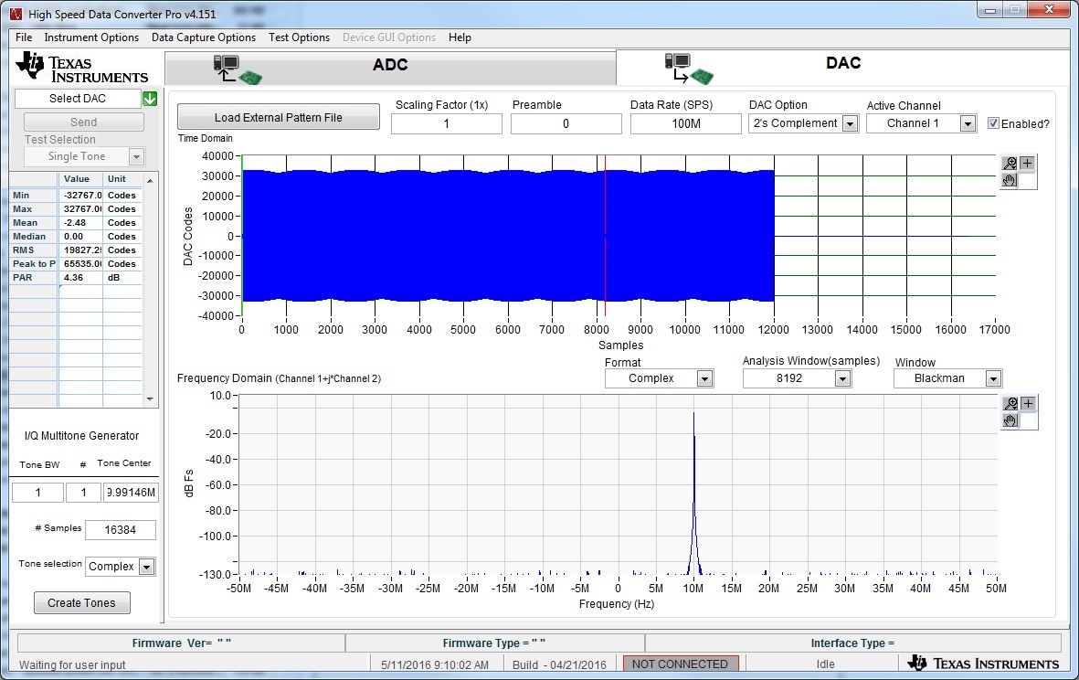
    Can you please try the attached csv file in HSDC Pro?  Just load it in using the load pattern option in the DAC panel.  It is a complex sine wave that is 16384 samples long, I zero the values from 12000-16384.  This should generate a sinewave with a gap from the DAC.  It is 10 samples per cycle.

    It should look something like this in HSDC Pro (ignore that I'm assuming 100Msps, this is irrelevant really and is only for FFT display reasons).  the actual output frequency will be 1/10 of your data rate.  If you like please send us your pattern and I can have a look at it.

    Sine_with_zeros.csv

    Ken

  • Kang,

    I apologize for the late reply, I cannot get into the lab very often.

    I used HSDC Pro to try and synthesize your csv file. I used the default DAC34H84 Firmware. The output does not look good, even with a sin. Here is the output:

    Troubleshooting this DAC previously, it was suggested we try removing the inductive coupling/HPF on the output. On channel A, we have done this, and are measuring the signal single ended, hence the disparity in the amplitude. Channel B is still the default setup.

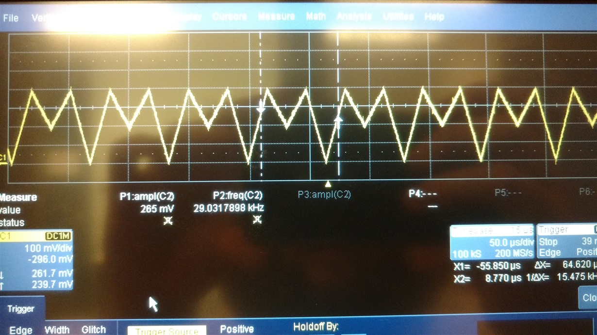
    Here are the results of additional experiments. I tested both a ramp and a sin wave, using the DAC34H84 Firmware included with HSDC Pro. Please see below, my issue presents itself as if it is frequency dependent:

  • Hi Ken,

    Have you seen my response? Do you know of a fix?
  • Kang,

    Have you seen the responses? Do you know of a way forward?
  • Nicholai,

    The output frequency response depends entirely on your output network such as filters and additional signal chains that you have on your system. We cannot support the analysis of the frequency response.

    To my knowledge, the DAC34H84 in your system is functioning correctly since some of the basic functions such as ramp and sinewaves are functioning correctly. This means the LVDS bus and all the DSP logics are correctly set. This is pretty much the extend that we can support at this point.

    If you still have doubts on your DAC34H84 setup, I suggest you use the default DAC34H84 setting file described in the user's guide + TSW1400 setup as a starting point. Then modify one thing at a time until you resolve the variables.

    -Kang
  • Kang,

    The output frequency response depends entirely on your output network such as filters and additional signal chains that you have on your system. We cannot support the analysis of the frequency response. 

    There is nothing in my output network. I am measuring directly the output of the DAC. As shown, is it expected that the DAC itself not produce good signals at that high frequency? It is well within the posted specifications of the DAC. My plot shows that, using the default firmware and the signal you sent, the output does not represent the input.

    The sin and ramp shown *only* function at very slow speeds. Note the order of magnitude difference in the periods.

  • Is there any suggested fix to this incorrect DAC behavior, using the TI created firmware and signal? Is it possible this is a faulty DAC if no good signal can be synthesized using TI firmware?