This thread has been locked.

If you have a related question, please click the "Ask a related question" button in the top right corner. The newly created question will be automatically linked to this question.

ADC12J4000EVM + TSW14J10 + KC705 TIMED_OUT_ERROR

Other Parts Discussed in Thread: ADC12J4000EVM, LMK04828, LM95233, TRF3765, ADC12J4000

Hi,

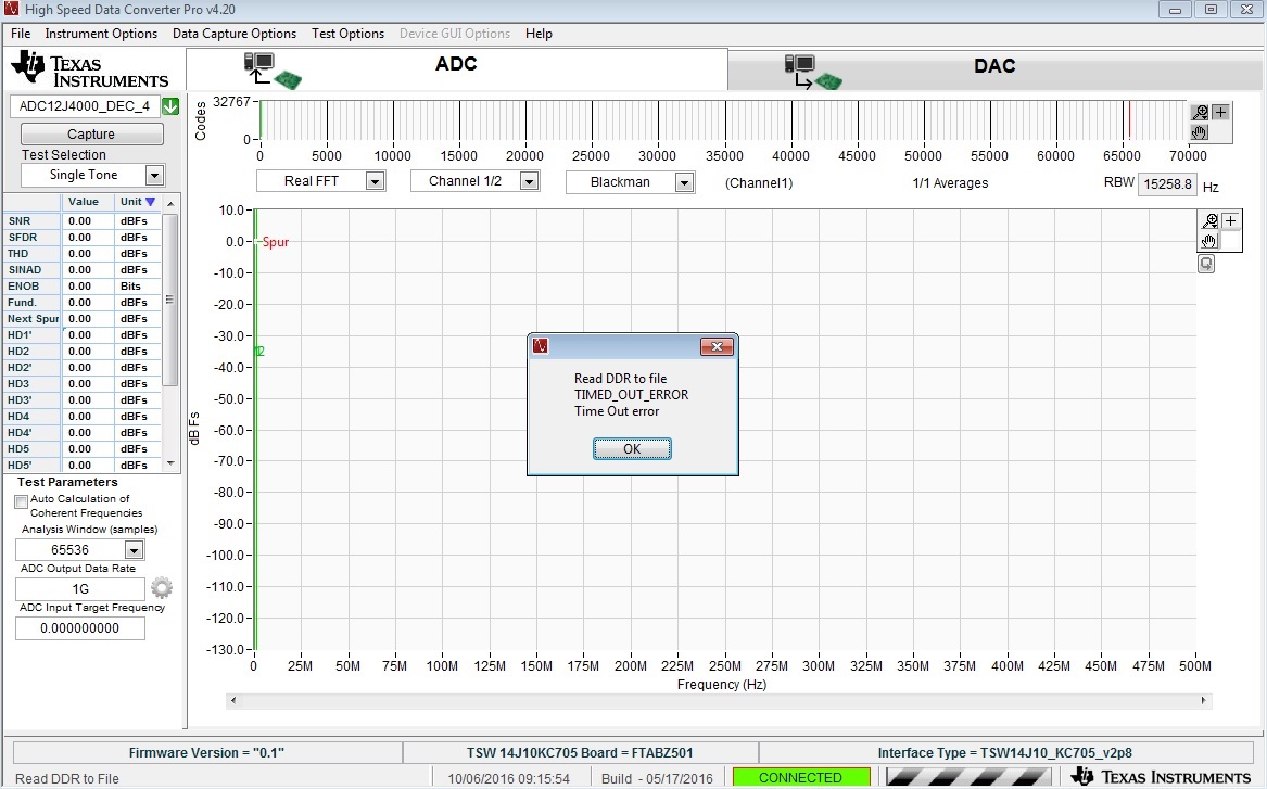
We recently try to capture data from the ADC12J4000EVM to the KC705 platform and display the captured data by means of the HSDC Pro GUI (GUI latest version, firmware version 2.8). We were not able to display the data because each time we click on the Capturing button the error message read DDR TIME_OUT_ERROR. We saw that when the button Capturing is click, the LED 2 goes low (the board is not under reset according to our understanding), the LED4 and LED3 go 0 1 indicating the mode ADC. Leds 5 6 and 7 blink. Everything seems good but any way at the end this error message appears. We also remark that the leds 0 and 1 are high - low. We undestand that this means the jesd_tx_sync goes high and the jesd_rx_sync goes low, Which means that the JESD_RX is either under reset or the synchronization with the JESD on the ADC side was not achieved! We tried to debug with the reference design version 2.8 and we received this. Pleas pay attention to the RX_RESET_REG  and the RX_SYNC_STAT_REG.

-------------------------------------
-- RX register Dump --
-------------------------------------
RX_VERSION_REG 0x06010200
RX_RESET_REG 0x00010001
RX_ILA_SUP_REG 0x00000001
...
RX_SYNC_STAT_REG 0x00010000
RX_ERROR_STAT_REG1 0x00000000
-------------------------------------

When we reset the KC705 board and click the Capturing button again, the LED 2 does not even go low. We suppose this is a  GUI bug?

We have also a TSW14J56 evaluation board and the data capturing under this board was successful. The problem arises only on the KC705 board.

We have also tested the things on our ZC706 board. Unfortunately the HSDC Pro GUI displays an error message concerning a labview ressource not found!

Please let us know if we must pay attention to some details when capturing data by the KC705. We did pay attention to the fact that the refclk and coreclk should be changed to adapt to the Xilinx design, but that didn't seem to resolve the problem.

Many thanks in advance!

Best Regards,

Tuan

  • Hi Tuan

    Can you provide more information regarding the ADC mode and clock frequency being used?

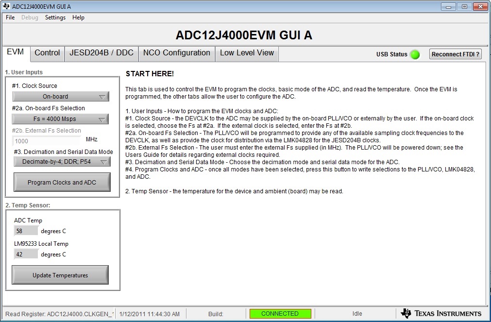
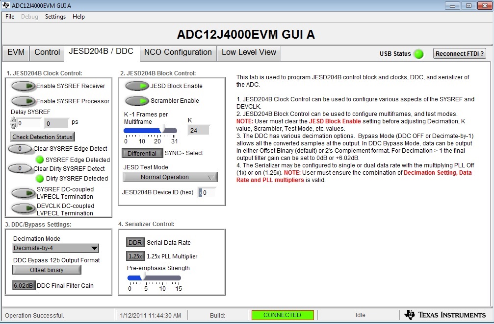
    1) Please provide a screen shot of the EVM tab of the GUI to show what is being selected.

    2) Have you made any configuration changes after the initial Program Clocks and ADC sequence, or is everything left at default?

    3) Were you using the same ADC EVM settings when you attempted to use the ZC706 board?

    Once we have the information we'll look into the problems you are seeing.

    Best regards,

    Jim B

  • Hi Jim,

    Thank you for your quick response.

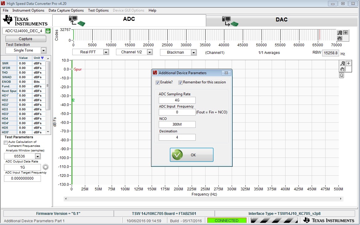
    The ADC sampling frequency is 4GHz, we have tested two configurations: Decimate-by-4, DDR, P54 and Decimate-by-10, DDR. For each configuration we tested both the default settings of the ADC12J4000EVM GUI and the setting where we reduce the coreclk by 2.

    1) Please provide a screen shot of the EVM tab of the GUI to show what is being selected.

    EVM configuration 

    JESD tab

    HSDC Pro configuration

    Error message

    2) Have you made any configuration changes after the initial Program Clocks and ADC sequence, or is everything left at default?

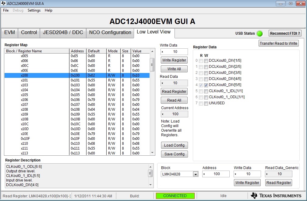
    We tested both. The default and the one where we reduce the coreclk by 2 (Address 0x100 of the LMK04828). The default value is 0x8, we have changed it to 0x10

    3) Were you using the same ADC EVM settings when you attempted to use the ZC706 board?

    yes we used the same ADC12J4000EVM.

    many thanks.

    Best regards,

    Tuan

  • Hi Jim,
    We reverify the frequency value of the coreclk and refclk coming from the ADC12J4000EVM and we found out that they were not correct values. We changed the devider value of devclk_out0 of the LMK04828 and everything works fine :).
    In conclusion, the default settings work fine for the TSW12J56. When the KC705 is used (decimated by 4 and by 10 for the actual supported configurations), the coreclk should be double --> reduce by a factor of 2 the value of LMK04828 register at address 0x110. Hope this will help someone another day.

    Best regards,
    Tuan
  • Tuan,

    What sample rate are you using in the dec by 4 case and what was your setting for add 0x110? Also same for the dec by 10 case. Did you use the default value for register 0x100? I am updating the TSW14J10 User's Guide and just want to verify these settings.

    Thanks,

    Jim

  • Hi Jim,

    The ADC salpling frequency is always  4 GHz so for decimate-by-4 case the sample rate is 1 GS/s and for decimate-by-10 case we have 400 MS/s.

    For the two configurations the coreclk values (reg 0x100) are lefted default.

    For the refclk we changed the value of reg 0x110 such that:

    - Decimate-by-4 case: the default value is 0x8. We changed this to 0x4

    - Decimate-by-10 case: the default value is 0xA. We changed this to 0x5

    Hope to see your updated user guide soon :).

    Tuan

  • Hi Jim,

    The ADC salpling frequency is always  4 GHz so for decimate-by-4 case the sample rate is 1 GS/s and for decimate-by-10 case we have 400 MS/s.

    For the two configurations the coreclk values (reg 0x100) are lefted default.

    For the refclk we changed the value of reg 0x110 such that:

    - Decimate-by-4 case: the default value is 0x8. We changed this to 0x4

    - Decimate-by-10 case: the default value is 0xA. We changed this to 0x5

    Hope to see your updated user guide soon :).

    Tuan

  • Hello,

    Can you share which configuration files to use for ADC12J4000EVM (for LMK04828, ADC12J4000, TRF3765 and LM95233), when connected to KC-705. I am trying to use 4Gsps, with no decimation as simple case. I am having difficulty in achieving SERDES lock.

    Thanks,

    D

  • Hi,

    I don't have any configuration files (at least I don't know if they exist) for the system. For the ADC, LMK, TRF etc. I use the ADC12J4000EVM GUI A of TI. When we click on configuration clock button it configures all the neccessary registers. You can then reverify the register values in the Low Level Tab. There is also a GUI log (double click on bottom left corner of the GUI) with which you can see which registers are written with which values. When you connect the ADC12J4000EVM to the KC705 it is noted that the value of reg 0X110 (LMK) must be reduced by 2 as indicated in previous post.

    In my project I don't use the decimation bypassed configuration. However, all the others work fine.

    I forget to mention that for the FPGA I use the reference design version 2.8 released by TI.

    BR,

    Tuan

  • Tuan,

    Are you having an issue with this setup? If so, I cannot exactly tell what it is by this post. What mode are you trying to use with the ADC?

    Regards,

    Jim 

  • I think you misunderstood my previous post. It was for deepak kumar32.
    BR
    Tuan
  • Hello Tuan,

    Thanks for your update. I am now trying to emulate the setup as above in post, i.e. 1Gsps with ADC sampling freq at 4GHz and decimation by 4 and 10 to get it down to 1 Gsps and 400 Msps. My question is whether I have to keep 1Gsps and 4Msps for my FPGA configuration? I will keep  QPLL of receiver of FPGA to be using 200 MHz.

    I will appreciate any more thoughts to help bring up my board.

    D