This thread has been locked.

If you have a related question, please click the "Ask a related question" button in the top right corner. The newly created question will be automatically linked to this question.

Analog input signal path design

Other Parts Discussed in Thread: ADC16V130, LMH6517

Hello.

I have some issue with differential filter design.

Our board  has the same configuration  as SP16160CH1RB Design Board. But the bandpass filter must be with the next  characteristics:

Center frequency - 18MHz

Bandwidth - 30MHz

Ripple <= 1dB

I am found some articles: SLWA053B  "Design of Differential Filters for High-Speed Signal Chains" and SBAA108A  "RLC Filter Design for ADC Interface Applications". With their help I make some converting with filter [From Differential Filter to Single-Ended].

Differential filter after converting:

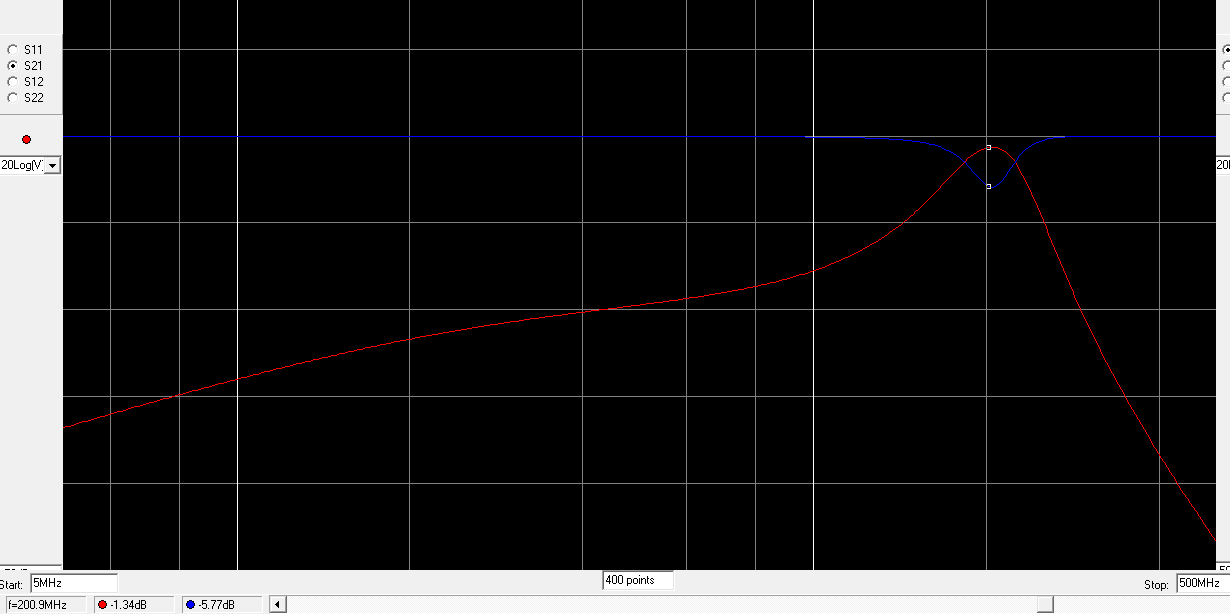
Simulation in RFSim:

Bandpass filter has the same profile as on Figure 7 [snau079], but centered on frequency 200MHz (no on 192MHz). Maybe it is mistake in my converting.

Tell me please, how  to change proposed in snau079 filter for my parameters ?

Maybe you have some formulas or program to calculate aforecited filter.

I am hope for your help.

Thanks.

  • Alex,

    A couple things to consider about the default filter design on the SP16160CH1RB:

    - Ideal simulated results do not include board parasitics, so the measured response will be slightly different than the ideally simulated response

    - The filter was not designed to have equal source and load terminations as it appears you are simulating. I believe it was designed to have 200ohm load (differential) and 50ohm source (differential), but then the source resistance was decreased to reduce the total insertion loss at little cost to the filter shape.

    I'm not sure that your filter specs are compatible with this filter archtecture because your filter Q is very small (Your bandwidth is very large compared to the center frequency) and therefore if may yield undesireable results.

    Please see the attached design guide for working with this particular filter architecture.

    4505.Tapped Inductor Filter Design v1.7.pdf

    Regards, Josh

  • Joshua,

    Thanks for interesting article.
    I can watch more detailed this article, on the next week.
    I am hope, to discuss some questions about this article with your help.
    Thanks.
  • Hello, Joshua.

    You are right, my filter specs are not compatible with this filter architecture [Tapped Inductor Bandpass Filter].
    I make some calculations such as in article "Tapped Inductor Bandpass Filter Design" and i saw this.


    I looked more another articles but i don't have an accurate understanding how to matching the LMH6517 and ADC16V130 in my band.

    Joshua, could you please give some suggestions above this problem.
    Thanks.

  • Alex,

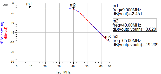
    Based on your frequency specs (3-33MHz), it seems that you would be better off with a lowpass filter plus AC coupling caps. Here's an example of what could work. I show the single ended version, and then the differential version (with a few added details). Of course, you should tweak the last load cap to compensate for the ADC's input capacitance.

    Regards, Josh

  • Many thanks for your great help. You're The Best.
    The last question: tell me please, what software you using for design this filter ?
    Thanks.
  • Alex,

    This filter was quickly designed in AADE Filter Design (free software), although I verified the design and simulated in Keysight ADS

    Regards, Josh