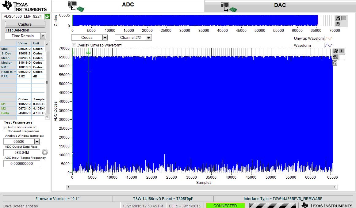
I have ran below configuration without any Analog inputs and no ext ADC CLK
Navigate to C:\Program Files(86)\Texas Instruments\ADS54Jxx EVM GUI\Configuration Files, select
the file called LMK_Config_Onboard_983p04_MSPS.cfg, then click OK. This programs the LMK04828
to provide a 983.04-MHz clock to the ADC. This configuration file also generates the required
SYSREF clock for both boards and the device clock for the FPGA on the TSW14J56.
5. Verify that the LMK04828 phase lock loop (PLL) is locked by checking that the PLL2 LOCKED LED
(D2) is lit.
6. Once the LMK04828 PLL is locked, press SW1 (ADC RESET) to provide a hardware reset to the ADC.
This switch is located in the middle of the EVM.
7. In the Low Level View tab, click Load Config. Select the file called ADS54J60_LMF_8224.cfg and click
OK. The TSW54J60EVM is now configured for no decimation and 8 JESD204B lanes.
8. Click on the LMH6401 tab. Set the Gain to "A" by entering the value in the box (see Figure 4) and then
click outside the box or press enter on the keyboard. This will provide 16 dB of voltage gain from the
LMH6401.
2. When prompted to select the capture board, select the TSW14J56 whose serial number corresponds
to the serial number on the TSW14J56EVM and click OK. This popup can be accessed through the
Instrument Options menu.
3. If no firmware is currently loaded, there is a message indicating this. Click on OK.
4. Verify the ADC tab at the top of the GUI is selected.
5. Use the Device drop-down menu at the top left corner to select ADS54J60_LMF_8224.
6. When prompted to update the firmware for the ADC, click Yes and wait for the firmware to download to
the TSW14J56. This takes about 3 seconds.
7. Enter “983.04M” into the ADC Output Data Rate field at the bottom left corner then click outside this
box or press return on the PC keyboard.
8. The GUI displays the new lane rate of the SerDes interface based off of the sample rate and other
parameters from the loaded configuration files. Click OK.
9. Click the Instrument Options menu at the top of HSDC Pro and select Reset Board.
10. Change the channel panel to Channel 2/2 to view the data from the LMH6401 path.
11. Click Capture in HSDC Pro to capture data from the ADC.
Attached is screen shot from HSDC
What is the reason for see full spectrum of noise?
1. Is this normal ?
No Analog input to ADC
See below screen shot
Plesae advice ASAP
Regards
Sam


