This thread has been locked.

If you have a related question, please click the "Ask a related question" button in the top right corner. The newly created question will be automatically linked to this question.

DAC3482: DC coupled output for DAC3482

Part Number: DAC3482
Other Parts Discussed in Thread: ADS4249, TIDA-00684, THS3217, DAC3484, DAC38J84, , DAC3484EVM

I got a high speed data stream (coming from ADS4249) where the data is in 2's complement.

I need to do a DC coupled output, DC-100 MHz. Output voltage range should be +/-4V with 50 Ohms termination (i.e. when it is 50 Ohms terminated, the signal on the 50 Ohms termination resistor would be +/-2V).

Can you suggest a DC coupled amplifier which can handle that + a diagram?

I intend to do DC and gain calibrations so minor DC offsets or small gain errors would not be a problem.

  • Check out THS3217 Diff-amp. This is a high bandwidth, high signal swing device. Reference TI Design TIDA-00684 which showcases a DAC with diff-amp application. The TI Design is centered on the DAC38J84 but that output interface is very similar to the DAC3484.

    --RJH
  • I'm using DAC3482 - not DAC3484. Is the same output as in DAC3484?

    The THS3217 datasheet is showing 2 X 25 Ohms resistors to GND in the input. Is it compatible with the output impedance of the DAC3482?

    I did not find any specs in the datasheet.

  • Yes, the DAC3482 has the same output as the DAC3484.

    Yes the 25 ohms is OK. The nominal Vcm for the DAC is 0.25V +/- 0.25V. The "spec" is related to maximum signal swing which is dependent on the load resistor, current setting on the DAC, and Vcm voltage. 25 ohm load per leg is typical. Check out the schematic on the TIDA-00684. This shows a usable interface encompassing a LPF with a 50 ohm resistor on input and output (thus effective 25 ohms per branch).

    --RJH
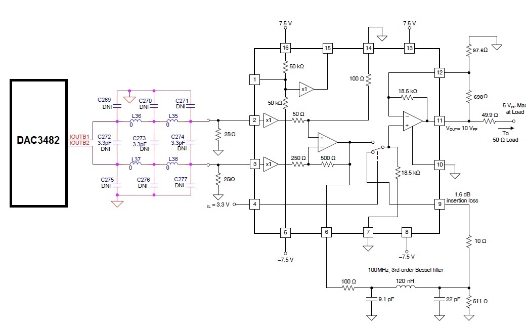
  • I need to get +/-4V output at no load or +/-2V output at 50 Ohms load. My desired bandwidth is DC-100MHz. DAC outputs samples at 1 GS/Sec after interpolation (X4). Do you think that this circuit would work?

    In my plan, the DAC outputs 0-20mA on each 25 Ohms resistor. Therefore, the output would be 0- 0.5V on both (differential) so a gain of 8 is required.

    On the THS3217 datasheet I see that high gain and high output swing will reduce the bandwidth.

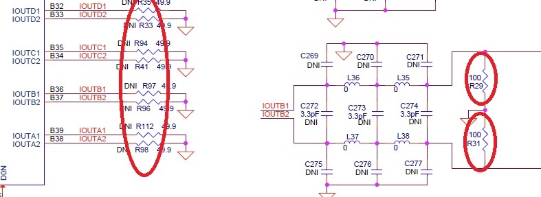
    On the DAC3482 evaluation module I see that they put 50 Ohms resistors after teh DAC and 100 Ohms resistors after the DAC:

    Maybe it would be better using 50Ohms resistors? I think that a large voltage swing at the DAC ouptut + lower gain would help to the increase the S/N ratio abd keep the bandwidth high.

    Please advice.

  • For your situation it is important to keep the output swing within the DAC's compliance voltage range. With a 25 ohm load and 20 mA full scale current you have the following situation:

    Max current = 20 mA; average current = 10 mA; Vcm = 10mA * 25 ohm = 0.25V.
    Voltage swing = 20 mA * 25 ohm = 0.5Vpp per leg => 1.0 Vpp diff
    Compliance voltage range per the datasheet is -0.5V to +0.6V (per leg)
    Max voltage is 0.5V so it is within compliance. Increasing the current or increasing the load resistor will likely exceed compliance.
    Note, the DAC3484EVM also has a transformer; composite impedance is 50//100//100 = 25 ohm.

    I recommend placing a 50 ohms before the filter (just after the DAC) and another one just after the filter. This will keep the filter nicely bounded by 50 ohm input/output impedance. From the DAC perspective, the load will be 50//50 = 25 ohm.

    The output sample rate is set to 1 GSPS. 4x interpolation puts input data rate at 250 MSPS. This is good for operating with a 100 MHz BW. Your input is 1Vppdiff. You want 4Vpp SE output. This translates to a gain of 4x (not 8x) which is 12 dB voltage gain. Per the THS3217 datasheet (Figure 1) the device can do over 4Vpp output significantly past 100 MHz at 12 dB of gain.

    --RJH
  • Thanks for your quick response. I agree with you about the 2X 50 Ohms resistors before and after the filter. I disagree about the gain:

    THe amplifier output (before the 50 Ohms connected in series to it) is +/-4V which means 8V ptp.

    Therefore, the gain is 8 and not 4.

    Does it change your answer?

  • I still think it is +/-4V. An +/- 8V would need a different part capable of 16V pp swing. This would have to run off something like a +/- 9 or 18 volt rails which is not trivial.

    If you are placing a 50 ohm in series which is creating a voltage divider then yes, I suppose you need 8Vpp. More gain and higher swing capability from the amplifier is needed. It doesn't seem like a good idea to throw away half the power. I think you could drive directly the 50 ohm load. In any event, if you want to pursue a 8Vpp device with required gain, I recommend that you post an additional question to the Amplifier forum where they are more knowledgeable about TI's amplifier portfolio.

    --RJH
  • I'm sorry but it seems like you did not understand what I tried to explain.

    I wrote "I need to get +/-4V output at no load or +/-2V output at 50 Ohms load". Never mentioned +/-8V.

    RJH wrote: "Max current = 20 mA; average current = 10 mA; Vcm = 10mA * 25 ohm = 0.25V.

    Voltage swing = 20 mA * 25 ohm = 0.5Vpp per leg => 1.0 Vpp diff"

    Therefore +/-4V (=8Vptp) divided by 1Vptp = gain of 8.  THS3217 is capable of a voltage swing of 8Vptp.

    As you may see in the drawing that I sent , Near the output it says "10Vptp" (this drawing was copied from  THS3217 datasheet.

    RJH wrote: "This translates to a gain of 4x (not 8x) "

    So I asked if the answer is still the same if the gain is X8 and not X4 as RJH said.

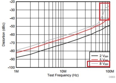
    I asked that because I saw different behavior for high gain values.

    For example, Harmonic Distortion is getting very high:

  • OK, yes somewhere I misunderstood the 4Vpp is with the series 50 ohm in place.  I understand your point.  You need/want 1Vpp Diff gained up to 8Vpp SE.  As you stated, then you need 8x voltage gain or 18 dB at a max frequency of 100 MHz.  It does indeed look like the THS3217 is capable of delivering 8Vpp at 100 MHz, although, as you noted, the device seems to be pushed to the limits as evident by the distortion characteristics.  You may need to adjusts the supply voltage to maintain reasonable performance.

    I do not have much experience with this device operating at the higher voltage swings.  I will close this ticket and encourage you to submit a new one on the THS3217 if you need additional assistance so that the proper amplifier experts can suggest the proper configuration or an alternative part for your application.

    --RJH

  • I close this ticket but if you know any other amplifiers that could work for my application, please send me their links in private

    Thanks for your help!

    Avi