This thread has been locked.

If you have a related question, please click the "Ask a related question" button in the top right corner. The newly created question will be automatically linked to this question.

ADC14X250EVM: SYNC signal for JESD204B

Part Number: ADC14X250EVM
Other Parts Discussed in Thread: ADC14X250

Hello,

I am using ADC14x250EVM and TSW14J56EVM combination to capture the read and capture the signals as shown in figure 2 of SLAU625. The goal of my project is to transmit the output of ADC (SO+/- pins) and SYNCb signals through fiber optic connection. I have successfully sent the serialized output signal through the fiber without any problem, however, I am having a lot of problem doing so with SYNCb. Hence, I have some questions regarding the SYNC signal:

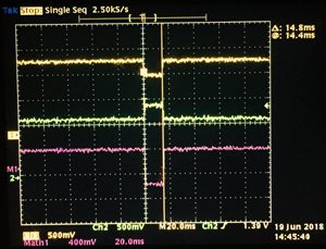
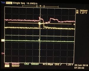
1. The SYNC signal is sent from the receiving side, which would be the TSW14J56 in this case. Could you please explain the physical aspect of how SYNC signal works - I know when connected the sync signal asserts and deasserts with a pulse of about 14ms width, figure 1(I connect my probes and push capture button in HSDC pro to obtain the SYNC signals). I expected this to be the communicated from the TSW14J56 board to the ADC, however, when I severed the connection, I could only see a pulse of about 3.5us width come out of the FPGA board, figure 2.

What does this mean? What is the sequence of creating the assertion and de-assertion? Which chip creates assertion and de-assertion - Is it that the ADC receives the 3.5us wide pulse from FPGA and then asserts and deasserts the SYNC signal or is it that FPGA asserts the signal through that pulse and then ADC deasserts it after 14ms? 

Figure 1. Original SYNC signal

Figure 2. SYNC signal

 2. The ADC configuration GUI allows control of SYNC over SPI. I can capture the signals successfully from HSDC pro if I switch to control of SYNC over SPI and hit the deassert button in ADC configuration quickly after hitting Capture button in HSDC pro. However, this is not practical. I was wondering if I could make the capture button in HSDC pro deassert the SYNC in ADC configuration GUI automatically? In other words link the two software and deassert SYNC when capture button is pushed but with certain delay. Has anybody in TI done such integrations in past?

I thank you for your help in advance.

Lizon  

  • The sync is issued by the JESD204B RX. So, in your case the FPGA will control the sync and ADC will respond to it. The sync is used to initiate a JESD link establishment and in this case FPGA is the master. You can find more about the sequence from these articles/videos:
    training.ti.com/jesd204b-physical-layer
    www.ti.com/.../slap161.pdf
    when you use a TSW14J56, the HSDC Pro initiates a link (by issuing sync) each time you hit capture. No, we haven't tried to connect the HSDC pro GUI and the ADC GUI as you proposed.
    regards,
    satish.
  • Hi Satish,
    I believe both of the GUI are built on Labview, am I right? Is there any kind of source code or resources that I can use to make these modifications on the GUIs myself? Are there any documentations on how to make changes in the source code?

    Thank you
    Lizon
  • Also for question 1, I have gone through the videos and articles that you referred many times in past, and did go through again. But I am still struggling to find the answer, so I am rephrasing my question, may be that will clarify:

    The SYNC is a unidirectional signal from FPGA to the ADC as per the documents. So if I look at the signal at the pins of FPGA : RX_SYNC_P and RX_SYNC_N (or corresponding FMC pins), it should spit out a link command (assertion) when capture button is pushed. I am looking at these pins using a oscilloscope at the FPGA side, and I realized that there is not signal output from the FPGA when the other end of the trace is NOT connected to ADC or left open, why does this happen? 
    Also, the DC offset value of the signal voltage varies as soon as the connection is altered, why does this happens?

    I have mis-communicated the problem in the very first post, the figure 2 in the original post is not when the connections are open, but when I attempted to send the SYNCb signal through fiber cable. When I tried to observe the sync signal from FPGA while the other end at the ADC was not connected, there was no signal. But breaking the connection caused changes in the DC offset values in the signals. 

  • Both the GUIs are built on LV, but the source code is not given out. I only see the installer for download.
    Per figure 53 and SYNC pin description in the device datasheet, the SYNC inputs have a dc-bias generated internally in the device. So, the dc-voltage on the pins will different between having it connected or not to the ADC. How much dc- offset do you see between the two pins?
    I think the SYNC signal type from FPGA is LVDS and in that case, a termination is needed to actually see a voltage change/swing. This could be the reason you don't see any SYNC activity when left open (current mode driver is seeing an open).
    There's a way to skip re-config (of the link) once its established. This can be done with a additional parameter in the TSW14J56 ini file. Will that help here? You can initiate and establish the link through the SPI the first time and then successive captures using TSW14J56 should work with out SYNC. You'll have to try this first, to be sure.
  • Skipping the re-config should solve my problem, how do I try this?
  • In the ini file, add "Skip Reconfig=1" to the first section (which has the # of channels, channel pattern etc).
  • I could not find the TSW14J56.ini but I found TSW1400.ini, where I added the skip reconfig line as follows (tried different combination of capitalizing and de-capitalizing the first letters of the words).

    Then I tried testing with continuous capture, couldnt get it to work. Should I have the TSW14J56.ini file?


  • If you are using a TSW14J56 board, then you should use its ini and that can be found here: C:\Program Files (x86)\Texas Instruments\High Speed Data Converter Pro_4p71\14J56revD Details\ADC files
  • Satish,

    I cant find the TSW14J56.ini file, I checked here where you referred and here as well: C:\Program Files (x86)\Texas Instruments\High Speed Data Converter Pro\14J56 Details\ADC files

  • I think I understand what you are saying is this:

    Since I am using ADC14x250 with TSW14j56, and in HSDC pro I select ADC14X250_LMF_112_LF as my firmware, I should go to this ini file and add the line, am I correct?

    But when I do this the syncb over SPI stops working completely.

    Lizon

  • Can you create a copy of this ini file, use the default one to establish sync over spi and then load the copy (with skip reconfig) and try.
  • Can you elaborate more, I can't follow. When I load the copy, the firmware updates in HSDC pro - so initialization occurs again with the copy and I can no longer establish connection.
  • add this line to your existing ini file and save it under another name. for the initial sync up, use the un-modified ini file and establish sync. Then load the modified ini file (in HSDC pro) and try capture. In this case, the fpga doesn't drop and re-establish the synchronization. So, you should be able to capture without issue of SYNC.

    this device has been designed to be in compliance with the JESD204B subclass 1 standard in which SYNC and SYSREF are necessary signals. So, if the above work-around doesn't lead to a fix, I would suggest using it per the proven design intent.
  • This worked, Thank you.