This thread has been locked.

If you have a related question, please click the "Ask a related question" button in the top right corner. The newly created question will be automatically linked to this question.

LDC1000 respiratory monitoring application troubleshooting

Other Parts Discussed in Thread: LDC1612

I am developing a respiratory monitoring application using the LDC1000 and an off-the-shelf respiratory inductive plethysmography band. The band contains a coil of wire. The concept of the application is to measure the inductance of the band as the chest or abdomen cause the belt to expand/contract during breathing.  The reasons I'm not using the off-the-shelf driver circuit for the band is 1) they're expensive; and 2) they include filters that I don't want to use.

I have managed to get the system working somewhat but it isn't very stable. In troubleshooting I have a few questions that I can't work out from the data sheet:

1) Output data rate: I am using the interrupt pin on the LDC to as a data ready pin. When I measure the output data rate on this interrupt pin I have found the data rate to be exactly 1/4 of the data rate that the data sheet specifies. i.e. when I set the response time to 6144, I get a data rate that corresponds to a response time of 1536. Has anyone else observed this?

2) Oscillation frequency of the LDC. What is the difference of changing the oscillation frequency and how do you select an oscillation frequency for a given application? I have an output from the LDC when I use an oscillation of 1V but if I increase it to 2v or 4v, I don't get an output from the LDC.

3) Filter capacitor. i) Does the filter capacitor effect the measurement of inductance or does it only effect the proximity output? ii) I understand how to choose the filter capacitor from the data sheet but I can not get the CFB pin to an amplitude of 1 V no matter how small I make the filter capacitor. 

4) Tank capacitor. Would the tank capacitor (I am using a ceramic disc capacitor) effect the series resistance of the LC tank circuit? According to the data sheet I have for the belt I'm using the series resistance should be 2.5Ω (I have confirmed this using a multimeter). However, when I work back from the proximity output of the LDC, I calculate the series resistance to be ~30Ω. This is a problem as to keep the resonant impedance within the range of the LDC, I have to use a LC tank capacitor that creates a resonant frequency of 10MHz (well above the recommended 5MHz limit of the LDC). I know I could add an inductor in series with the respiratory belt, but I'd like to understand why I'm finding such a high series resistance. If it was closer to the belts data sheet then I could get the system working without an extra inductor. 

I'm a mechanical engineer by background so excuse me if any of the questions are obvious. Any help would be very much appreciated, I have been trying for weeks trying to understand how to get this chip working in this application!

  • Hello,

    Let's start with the basics.

    Could you please let us know the inductance and Rs of the coil? Ideally, as a function of frequency, otherwise at 100kHz and 1MHz should suffice for now.

    Great application, BTW! Let's work together to have it successfully completed.

  • Hi, thank you for offering to help!

    The values for inductance and Rs of the coil that I have are 2.827 micro H and 1.509 Ohm respectively. These were taken from the patent application which describes the belt that I'm using.

    I don't have a way to determine these values myself except to use the LDC itself.  I tested the belt using oscillation frequencies of  ~100KHz and ~1MHz as you suggested with two different tank capacitor values (68 microH and 100 microH):

    At 100 KHz and a 68 microH capacitor I get: Rs = 8.84 Ohm and L = 2.702 microH

    At 100 KHz and a 100 microH capacitor I get: Rs = 18.61 Ohm and L = 2.2 microH

    At 1 MHz and a 68 microH capacitor I get: Rs = 11.11 Ohm and L = 2.703 microH

    At 1 MHz and a 100 microH capacitor I get: Rs = 21.1 Ohm and L = 2.19 microH

  • I'm sorry, it's not clear to me what exactly you have done:

    1) Caps are measured in farads

    2) How did you measure Rs using LDC1000?

    3) For a given coil and a cap, only one oscillation frequency is possible, given by a resonance frequency formula.

    Could you please clarify?

  • I'm sorry hopefully the following clears things up:

    1) All of the capacitance values units should be pico farads (it was late last night and I clearly wasn't thinking straight!)

    2) I calculated it by working back from the proximity value output of the LDC1000. From the proximity value I calculated the Rp value using the formula on p11 of the data sheet. I then calculated Rs using the formula given on p9 of the data sheet (Rs = L / [Rp * C]).

    3) I varied the Min Resonating Frequency of the LDC1000 (Register name: Sensor Frequency). It was my guess that his changed the frequency applied to the coil. 

  • Ok, that makes more sense :)


    Let's try the following : use 100pF, and set the RpMIN register setting to 3F, RpMax - to 12 / 14, and see if you can get it producing nice data.

    If you can post a scope screen at INA and CFB pins, it would be very useful.

  • And regarding the Rs value - it's high, because we operate at fairly high frequency, where skin effect is very significant.

    All in all, the whole system seems to be pretty close to the Rp low limit, and in the end we may need to add a serial inductance (I would start with 10uHr - it will definitely allow proper operation, and then check if we have enough sensitivity)

  • OK good news, I have a pretty nice signal now. 

    I tried a few things to get there:

    1) 100pF tank capacitor. With this setup, I did not get any output from the LDC (oscillator was running but no data was produced) when I tried to measure the output of the INA or CFB pins using an oscilloscope, or when I wore the belt. (the values I posted in my previous post were taken while the belt was on a desk, not a great idea in hindsight). 

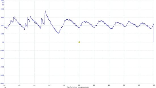
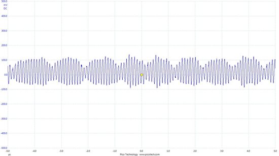
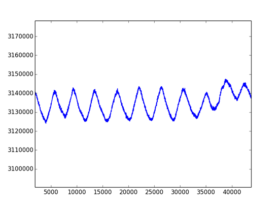
    2) I used a 68pF tank capacitor, set the LDC sensor frequency to 8.46MHz, set the LDC oscillation amplitude to 1V, the response time to 6144, Rp min to 0x00 and Rp max to 0x14. I then varied the value of the filter capacitor (the one connected between the CFA and CFB pins). I could only get a reasonable output at CFB using a 9.9pF capacitor. I got an almost flat output using either a 6.8pF or a 20pF capacitor. See below for the different outputs that I measured using my scope when using the 9.9pF capacitor:

    The CFB pin:

    The INA pin:

    And finally an example of the change in inductance during normal breathing (the y-axis shows inductance in pH):

    This is great progress and thanks for your help so far! I still have a few things that I'm curious about, particularly to see the noise in the above output can be reduced at all. 

    1) How important is the output at CFB? In the data sheet it says that a peak to peak output of 1V is desirable. The best I can get with the current setup is shown above but I'm wondering if that could be improved if its worth trying a series inductor to see if that improves it.

    2) What effect does setting the amplitude of LDC have on the output. I read in another post that bigger is better, with the trade off being increased power use of the chip. My current setup does not work if I use an output bigger than 1V but I have no idea why. 

    3) With a series inductor I should be able to reduce the resonant frequency of the LC tank circuit. Would bringing the sensor output within the data sheet recommended range (5MHz) help the output?

    Thanks again!

  • 1st, let me congratulate you on a very good progress!

    Now, I'm quite surprised that you see anything with Rpmin setting of 0x00 - is this truly correct? For the best results I would suggest you to use 0x3F!

    The higher amplitude will increase SNR, so yes, it's something to work on. But if you have to add a series inductor to increase the oscillation frequency, it may negate positive effects of the amplitude increase

    Reducing the frequency by adding the series L will not help.

    When do you plan to go to production, we may have a more suitable part by that time?

  • Thank you! 

    Sorry, you're right with RpMin, I have it set at 0x3F (I have too many numbers in my head but I really should double check before posting!) 

    Thanks for your additional answers. Aiming for a higher amplitude sounds worthwhile. I'm still not sure why it doesn't work currently, does increasing the amplitude also change Rp and therefore push it out of range? 

    I'm still also unclear about the output of CFB, does that have a bearing on the SNR? 

    I have one last issue that I forgot to mention in my last post post. Whenever I touch my laptop I get shift in the inductance output. Eventually this will be a battery powered portable device so this should be a problem but I'm interested as to why it happens. Any ideas?

    We're still in the concept selection phase of R&D but all going to plan we'll have the final design finished by the end of the year. If you think there maybe more suitable parts available in that time frame I would love to hear about them. The respiratory sensor is only a part of the device we're designing, I'd be happy to tell you more in case you had any other suggestions on parts we might try. If you'd like to talk more about it can you send me a private message? 

  • Hello,

    I have referred your roadmap inquiry to our marketing, they will get in touch with you.


    Higher amplitude needs higher driving current, which is limited in LDC1000 (hence the requirement on Rp range)

    Proper amplitude on CFB ensures the most stable operation point, and thus, highest SNR.

    I have tried the same on my laptop now, and do not see any changes. Does yours have metal case? Mine is plastic...Perhaps some ground loop issues?

  • Hi, sorry for my delayed response. 

    Thank you for the explanations, that makes sense. I can't get a reading off of the CFB pin without altering the output of the LDC (I've tried using a 1K  series resistor with the scope) so I'm not sure how accurate my reading of CFB is. I increased the filter capacitor to 100pF and seem to have a reasonably good signal, good enough to work with anyway.

    I do have a metal cased laptop and also thought it could be a ground loop issue. I tried using a bluetooth connection between our LDC system and the laptop and that definitely reduced the problem. There is still some interference when I touch the laptop but it can be removed with some minor filtering so its not a big practical issue.  

  • As long as CFB signal is in a ballpark of 1V, all is good. Don't worry about the output shifting.

  • I'm delighted to find this thread as I have a similar application.

    However, it's normal to disconnect the sensor from the band in order to replace it, and to fit it around the patient. This will leave the connections to the LDC1000 exposed to static etc., and if the device is powered it will presumably stop oscillating.

    Do you have any recommendations for protecting the inputs, and for recovering normal readings when the coil is reconnected ?

  • Hi Adrian,

    I would put some clamps for ESD.  Please see this thread:

    http://e2e.ti.com/support/data_converters/inductive-sensing/f/938/p/303148/1056642.aspx

    Thanks,

  • Hi, I'm having similar issues with the same kind of application.

    I intend to measure breathing using a inductive belt. The problem I have is that the Frquency counter only ranges from ~3995 to ~4050 with my setup.

    What can i do to increase the resolution and/or sensitivity?

    My setup:

    C_Tank: 470 pF
    C_Filter: 100 pF
    Belt: ~3.1-3.2 uH
    -> LC-freqeuncy: ~4.05 - ~4.10 MHz

    Responstime: 6144
    Ampl.: 4V
    Rp_Min: 1026
    Rp_Max: 13xx (not at work right now)
    Freq_min: 221 (4MHz)

    If I choose a higher C_Tank (1nF) I get nothing at all (Rp too low?). If I use a lower capacitor (33pF) i also get nothing (Freq too high?). I also tried varying the settings of the LDC but nothing ever changed the freq. resolution. I only got the proximity to vary between 12500-14250, but that's not the signal i was hoping to use...
  • Hello Silvano,

    Are you using L measurement only? Would you be open to switch to LDC1612 in this case?
    You can increase the reference clock of LDC1000 to 1MHz and try to decrease Rp range if possible.

    Best Regards,
    Natallia Holubeva
  • Hello Natallia,

    regarding the LDC1612 I unfortunatelly dont have an I2C interface left for the current application.

    What do you mean increase the reference clock to 1MHz; the crystal on XIN/XOUT already runs at 8MHz (as stated in the datasheet with no information given on the range, sadly)?
    Also decrease the Rp range - it's already at the narrowest possible if I narrow it further i get Rp_Min = Rp_Max?

    regards Silvano

    PS: Angus mentioned to be using 2uH (belt), C_Tank = 69pF and C_Filter = 10pF which worked for him but is totally out of range? - will give those values a try anyway i guess.
  • Silvano,

    I am sorry, I meant 8Mhz clock (maximum for LDC1000). You are correct by keeping RP range to minimum. Please, trying decreasing the filter capacitor to 33pF if possible.

    Best Regards,
    Natallia Holubeva