This thread has been locked.

If you have a related question, please click the "Ask a related question" button in the top right corner. The newly created question will be automatically linked to this question.

Multiple LDC1000 on SPI

I successfully connected my Arduino to an LDC to configure it and read the results.

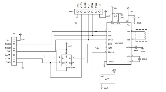
I need to connect multiple LDCs on the same SPI bus (about 10 separated by at least 30cm). I am using a shift register (with D-type Flip-flops to select each LDC)

But as soon as I connect a second LDC on the bus, I receive incorrect data, as if both LDC were enable at the same time and interfering. And if I disconnect the second LDC and I read it anyways, it actually reads the first one again (with correct values). As if the shift register is working badly.

I tested the shift register (with slow pulses), and it works perfectly, even the first LCD is correctly configured.

Any ideas? 

  • Hi Andres,

    We have used two LDC1000 in an application that shares the SPI bus, and found no problem.

    Please attach your schematics so that we can take a look.

    Best regards,

    Don

  • Hi, this is the schematics. The idea it two connect N number of devices in series.

    I tried pull-up and pull-down R (10k-30k) on the MISO line. As well as a R (330) in series.

    The datasheet mentions about the SDO: "It is high-z when CSB is high", it is evident that including a second LDC on the SPI bus affects the SDO data. My test shows exactly that.

    So how to handle the the SDO and/or CS  properly, making sure that on the SDO only one LDC is transmitting and not interfering? Or what am I missing.

    Thanks

  • It is not clear from the diagram what the timing of the CSB look like. What I would suggest to do is to use a demultiplexer logic CI (such as 74HC138, 74HC154) to distribute the CSB control. Timing wise, select the demultiplexer output first before setting CSB low.

    Good luck!

    Don

  • Hi Don,

    I am using D-type FF as a shift register, shifting one bit, so after I send a pulse to the FFs (CS low on the first LDC), I then begin the SPI transfer. Then the uC sends a second pulse to select the next LDC.

    In each iteration I make sure I to set all FFs Q' (CS) high before beginning the reading process.

    I chose this shift-register solution since I only have two lines to control the CS (besides 3 lines for SPI and two for power/gnd), and be able to control N number of them, physically separated (that is, each one with their own 'CS selector'). What I am struggling with is, if the FFs seems to be working good, and the LDC are correctly programmed (one by one, ergo MOSI line is ok), problem appears when reading.