This thread has been locked.

If you have a related question, please click the "Ask a related question" button in the top right corner. The newly created question will be automatically linked to this question.

LDC1000EVM at 40kHz (151uH + 1.17 ohm // 0.1uF ) How much CFB should I put?

Other Parts Discussed in Thread: LDC1000EVM

I have a air core solenoid coil ( L=151 uH, Rs = 1.17 ohm ) connected to parallel capacitor ( C=0.1uF )

Resonant frequency = 40 kHz

I connected it to LDC1000EVM and I can measure the inductance all right. 

(Sampling frequency setting is at 18 Hz )

But the proximity Data always stays at the it's maximum value. 

(Changing the Rp max, Rp min setting dosen't change the proximity data at all.)

I haven't changed the C18 value yet.  It is 20pF --- initial value.

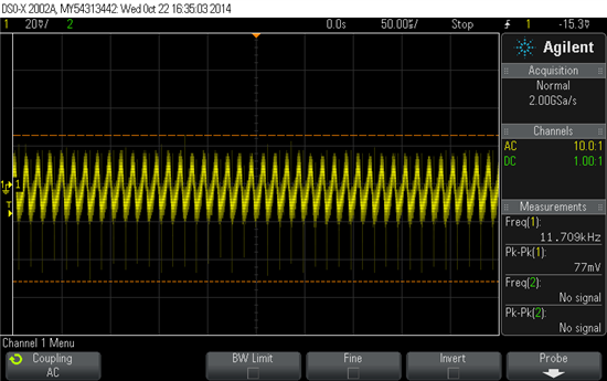
I attached the waveform at the CFB below.

Vp-p is very small - only 77mV including noise.  

So, I should reduce the C18.  But it is already 20pF.  Should I remove it?

Should I change the C18 ( CFA - CFB ) ?

What value do you recommend?

Hope to receive some answer soon. 

Below is the wave form between the coil. 

This resonant signal looks all right.

  • Hello Koyo,

    Could you please try increasing the value of Cfb? You can refer to the page 13 of the Datasheet and follow the procedure below:

    1. Start with a large filter capacitor. For a ferrite core coil, 10nF is usually large enough. For an air coil or PCB

    coil, 100pF is usually large enough.

    2. Power on the LDC and set the desired register values. Minimize the eddy currents losses by ensuring there

    is maximum clearance between the target and the sensing coil.

    3. Observe the signal on the CFB pin using a scope. Since this node is very sensitive to capacitive loading, it is

    recommended to use an active probe. As an alternative, a passive probe with a 1kΩ series resistance

    between the tip and the CFB pin can be used.

    4. Vary the values of the filter capacitor until that the signal observed on the CFB pin has an amplitude of

    approximate 1V peak-to-peak. This signal scales linearly with the reciprocal of the filter capacitance. For

    example, if a 100pF filter capacitor is applied and the signal observed on the CFB pin has a peak-to-peak

    value of 200mV, the desired 1V peak-to-peak value is obtained using a 200mV / 1V * 100pF = 20pF filter

    capacitor.

    Best Regards,

    Natallia Holubeva

    Application Engineer

  • Hello,

    Please remember that the RP value measured by the LDC1000 is the AC resistance, not the DC resistance, so there may be some difference between the RP you expect and the actual RP. If you set the RPMIN to the lowest resistance and the RPMAX to the highest resistance, and then try to determine the proper CFB value.

    What type of capacitor are you using? You will want a high-quality dielectric. Also, the capacitor should be placed close to the inductor.

  • I checked the AC resistance of the coil at 40 kHz.  It is a little bigger than DC resistance. 

    I found that Rp is 837 ohm.  A little bigger than 798 ohm.  Maybe there should be more margin. 

    So, I changed the frequency from 40 kHz to 60 kHz.

    I decresed the C from 100000 pF to 47000 pF. 

    Rp in now 1674 ohm --- much bigger than 798 ohm.  

    Then I increased the C18 ( CFB ) from 20pF to 100pF than  470 pF.  

    Now the CFB voltage is a little below 1.0 Vp-p.

    I soldered 1.8 k ohm series resistance to CFB terminal as below to monitor the waveform.  

    Then I monitor the CFB by oscilloscope. 

    Ch1 is waveform at INB.

    Ch2 is waveform at CFB.  

    Voltage = 590 mVp-p almost 1.0 Vp-p

    This waveform is the voltage between the coil ( between INA and INB )

    Is this the waveform when the LDC1000EVM is configured correctly ?

    Or shoud I change something ?

    There is one more problem.  

    Inductance value is not stable.  

    L is changing slowly between 125 uH to 128 uH.  

    How can I get more stable inductance value?

    When I tried at 40 kHz, although the CFB voltage is very low, inductance was 10 times more stable. 

    What should I do?

  • Hello,

    The INA/INB signal you have shown is reasonable. I have two recommendations on the L stability - first, it looks like your inductor is a few cm away from the LDC1000; you should twist the wires between the LDC1000 and the sensor.

    Next, it is important to use a high-quality capacitor for the sensor; I don't know if the disk capacitor you are using is a NPO or C0G grade, but that is the recommended type of capacitor. Finally, the sensor capacitor should be as close as possible to the sensor.

    I hope this helps.

    Regards,

    ChrisO